Bogen Paging - Wiring Setup
This guide will walk you through the wiring setup for your Bogen Paging System
Step-by-step guide
Note: Click any image to see it larger.
- Unbox and wall-mount the equipment.
Recommendation: Mount the included Polycom Phone within 12 inches of the Paging Amplifier
-
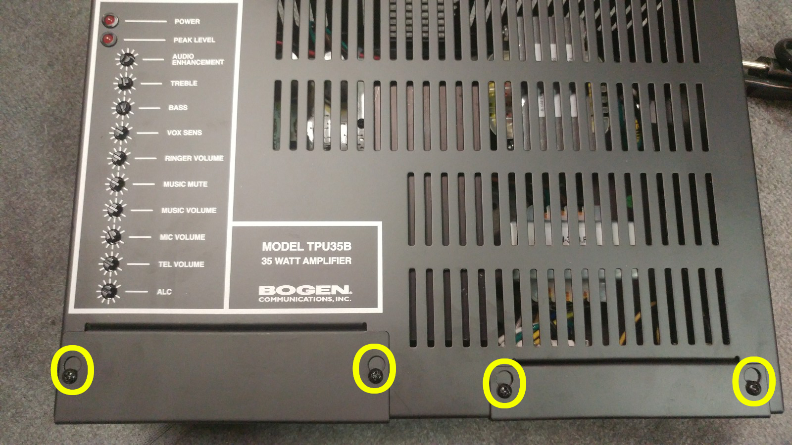
Loosen (but don't remove) the four screws holding down the wiring terminal cover-plates as shown. These plates should now be removable. Keep these plates for completing the installation and re-covering the wiring terminals when wiring and testing are complete.

-
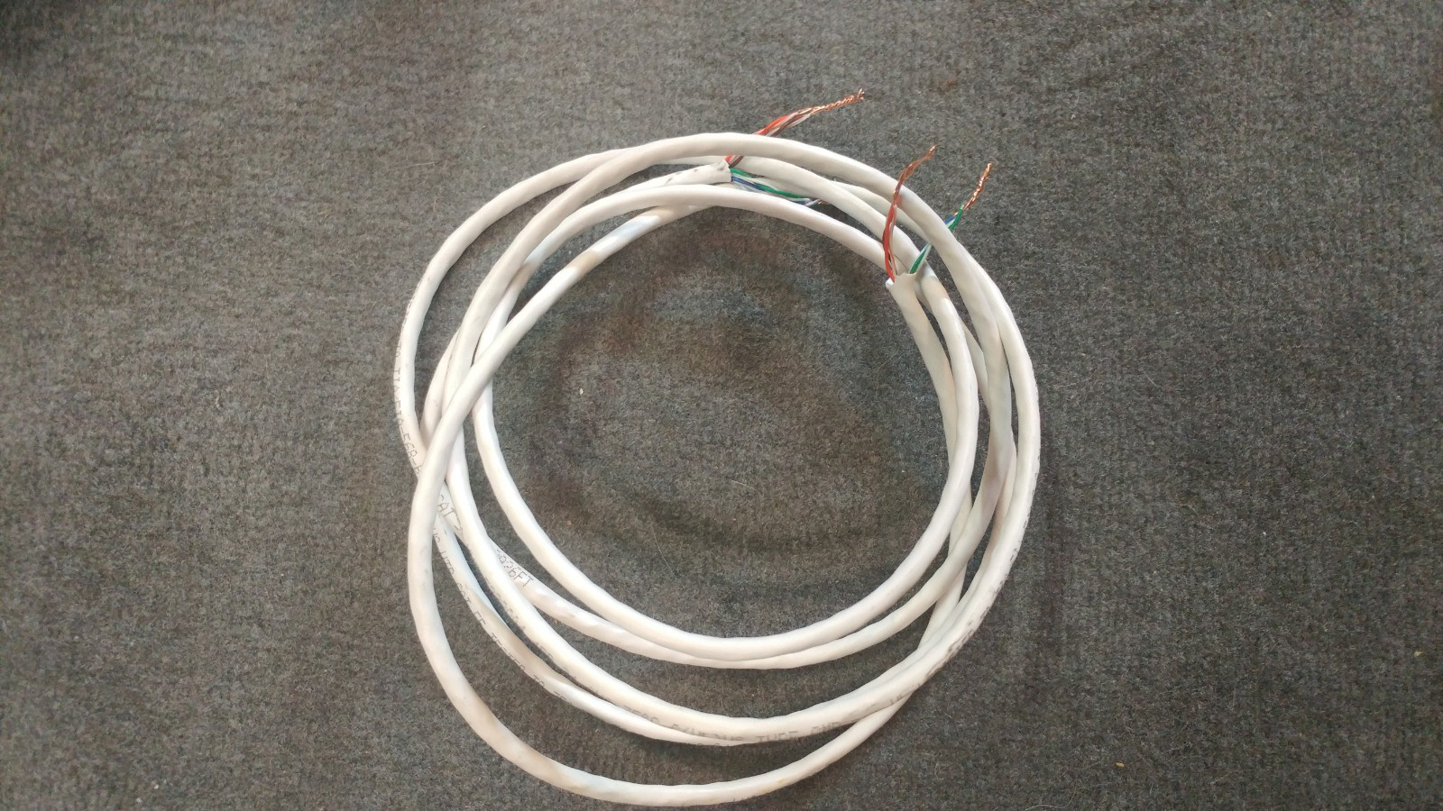
You may have received a 'test wire' with your package. If your test wire is a Category 5 type wire (Standard Network/Ethernet wire), you'll notice the Brown/Orange pairs are twisted together, and the Blue/Green pairs are twisted together. Leave these pairs twisted. This is done to make an equivalent of a 12 gauge wire to safely carry the 70-volt speaker signal. If your package did not come with speaker wire, use this as a guide to make your own speaker wire using standard Category 5 Networking wire.

-
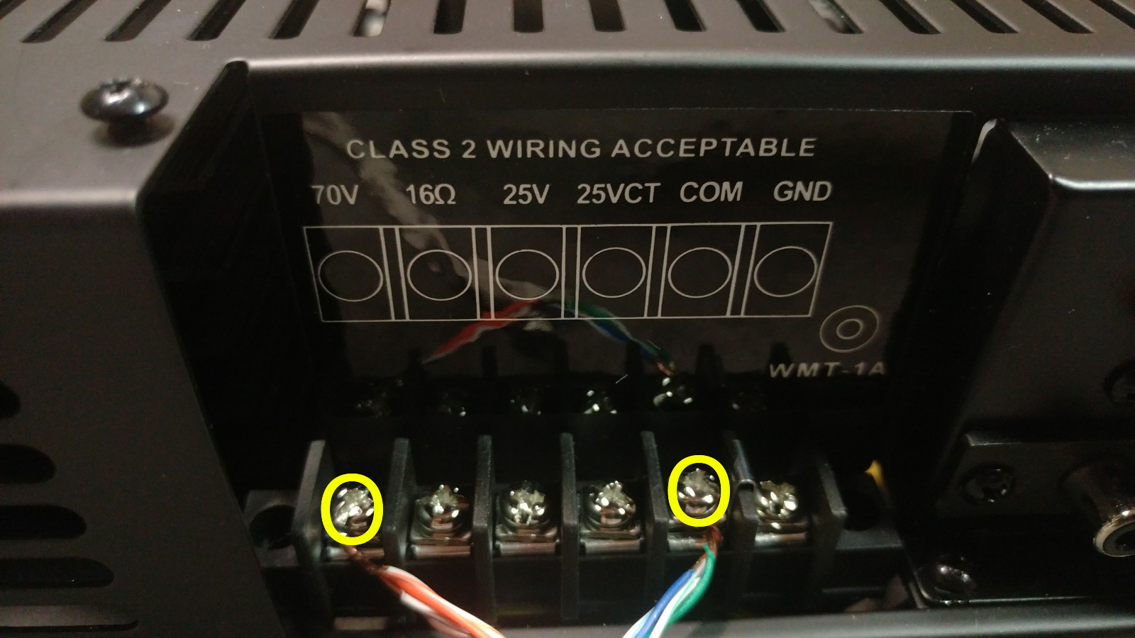
Use the 'test wire' to connect the amplifier to one of the speakers as shown below. Note which color combinations are connected to 70v and which are connected to COM. You will need to make the same connections on the speaker side. After testing, and for the final speaker wire installation, you will use these same connections as shown below.
If you are using more than one speaker, you can connect all sets of speaker wires to the same terminals, which will connect your speakers in parallel. If you are unable to fit all the speaker connections on one terminal, which will be the case when using more than two or three speakers, you will connect your speakers in parallel with the Speaker Hub.
Make all wire connections to and from the amplifier with the POWER OFF.
Also, Unless otherwise noted, your paging system is a 70 Volt System. Do not make any connections to 16 ohm, 25V, 25VCT, or GND otherwise the equipment may become damaged. Damaged equipment caused by incorrect wiring is not covered under any warranty or service plan. If you have any questions or concerns, please contact your vendor for technical support.
-
Use the 'test wire' to connect to the speaker as shown. Your specific terminals may be different than the ones shown here, depending on what speakers are part of your package. The important part is to match the total power draw with the maximum power output of your amplifier. In this example, we are using a 35-watt amplifier. If using Cat5 wire, use the Blue/Green pair to connect to COM. If you are using standard speaker wire, use the negative (black or non-stripe) wire to connect to COM. If you are connecting one single speaker, use the 16W terminal to make your connection from the amplifier's 70V output as shown. If you are using two speakers with a 35-watt amplifier, to ensure longevity of the equipment, use the 8W terminals.
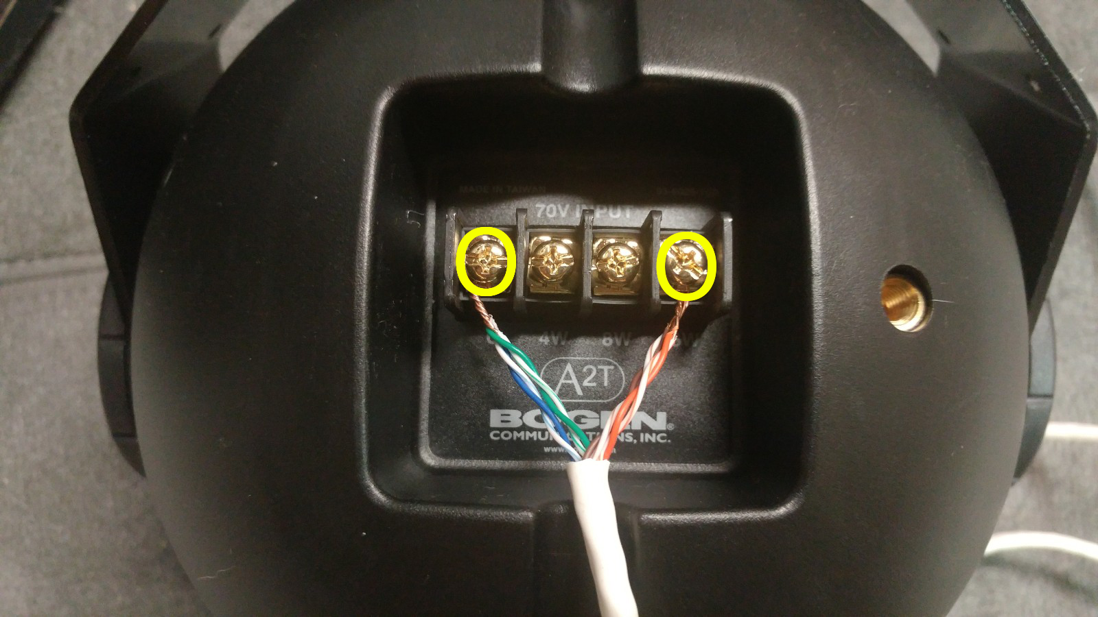
When connecting multiple speakers to your system for better coverage of your facility, note the maximum power load that will be put on the amplifier.
When making a connection to a 16-watt tap, this will use 16 watts of power from the amplifier. You will see the maximum power load listed on the body of the amplifier. Depending on the model, your amplifier may be 35 watt, 60 watt, 100 watt, or 250 watt.
If for example, your package is a four-speaker and 35-watt amplifier system, you CANNOT use the 16-watt tap on all four speakers (Because [16 x 4 = 64] and this is greater than the MAX of 35).
You CAN however use the 4-watt tap on all four speakers (Because [4 x 4 = 16] which is a comfortable 47% of the max),
Or, you can have one speaker use an 8-watt tap, and the others can all use the 4-watt tap. The total watts of all speaker connections cannot exceed the maximum power load of the amplifier, otherwise serious equipment damage will occur. The absolute maximum for speaker load is 90% of the amplifier rating. Ideally, you don't want to be higher than 80% of the amplifier rating to ensure the highest reliability of your equipment. -
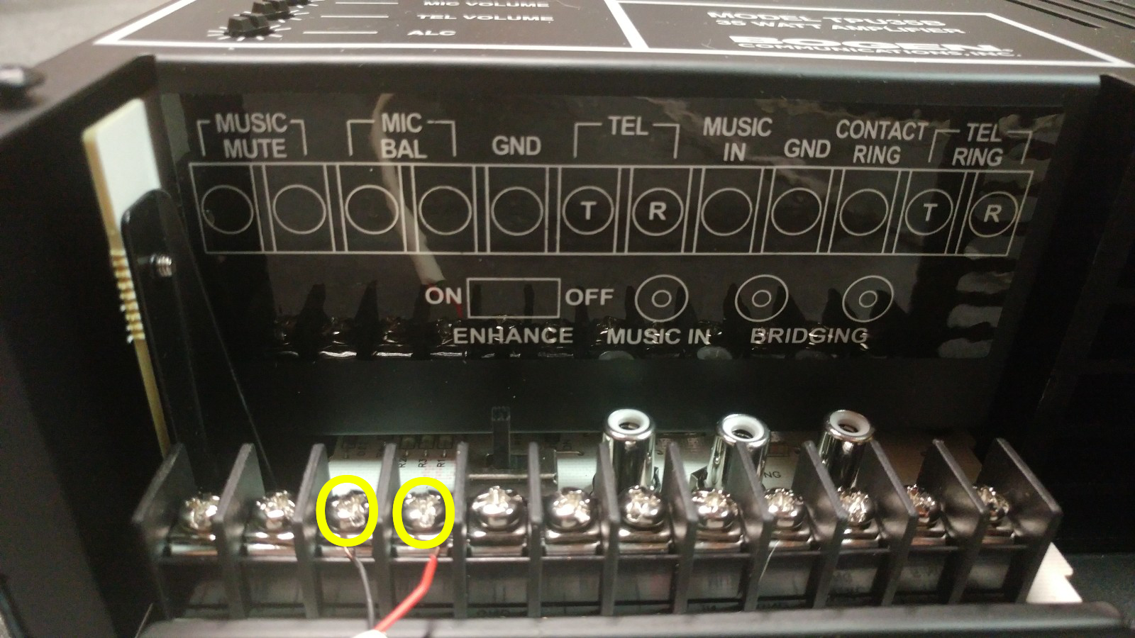
Connect the mic inputs with the included Polycom to Bogen cable. Use the guide below for making the connection to the amplifier. Your type and color of cable may vary. Connect the red or positive side to the right-hand terminal for MIC. Connect the black or negative side to the left-hand terminal for MIC.
-
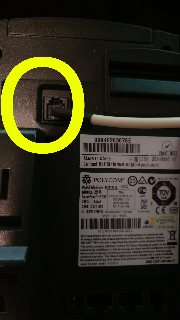
Connect the rj22 jack to the back of the Polycom phone, to the 'Headset' port as shown.

- Plug the Polycom phone into a network port or directly into the network switch. If your Polycom phone did not come with a power adapter, the power will be provided by the network switch.
- Test the volume of the speaker by either dialing your paging extension or calling the extension of the paging phone directly. Make sure the phone is in headset mode when testing the speaker volume.
-
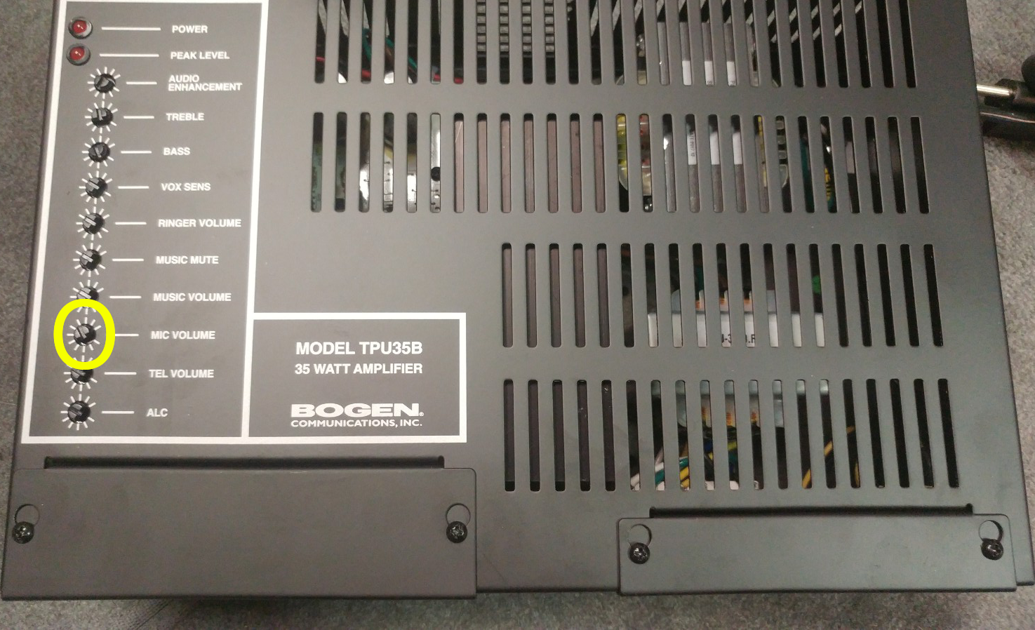
If the volume needs adjusting, make sure to not increase the headset volume on the Polycom past 50% of the maximum. Increasing the volume more than this on the phone may incur unwanted distortion in the output sound. If you need to increase the volume of the speaker, use the MIC knob on the amplifier.
Make sure to increase the volume in SMALL increments. Overdriving the speakers may cause serious damage to the amplifier or the speakers. Equipment damage due to overdrive is not covered under any warranty or service plans.

No other adjustments should be needed other than the MIC volume. All other values have been set by your vendor prior to shipment. If you feel that your paging system is not performing the way you expect, please contact technical support prior to making any additional adjustments.
- After testing, you may now replace the connections with the final speaker wire connections. Make note to keep the signal wires going to the same places they were when testing.


No comments to display
No comments to display