Web Portal
- Getting Started
- Conceptual Overview
- Tutorials
- Web Portal Introduction
- Users
- Departments
- Extensions
- Phone Configuration
- Devices
- DayNight Groups
- DayNight Schedule
- Hunt Groups
- Hunt Group Members
- Inbound CallerID Remap
- Phone SysDial Directory
- PhoneMap Groups
- Phone Map Members
- Voicemail
- Call Logs
- Support and Troubleshooting
- Cook Book - Recipes
- Overview
- Generate Reports
- ScreenPop User Onboarding
- What's New
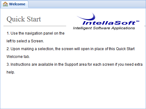
Getting Started
The web portal is the core of the Intellasoft Platform. It is the central place for configuring everything from users to schedules to extensions.
Table of Contents
This documentation is split up into 3 main parts: Tutorials, How-To Guides, and Reference. Start by following a few tutorials to become familiar with the basics. Below is a table of contents.
- Conceptual Overview
- Tutorials
- How to Guides
Next Steps
Conceptual Overview
The web portal is divided into screens (selected from the navigation panel on the left). Each screen often contains a table of entries. For example, the Users screen contains a table of users. The columns along the top correspond to each configuration option and the rows correspond to each user.
A screen can also contain other sections, sometimes used for additional configuration options or other times to display additional information. As an example, the extensions screen has an "additional settings" panel on the left with more options that do not fit in the table.
Basic Configuration
To modify any table, click the "new [entry name]" button at the top or modify an existing entry by double-clicking the entry.
To delete an entry, look for a red X (often in the far right column) and click it. A dialog will pop up confirming that you wish to delete. Click Ok to delete.
Next Steps
Tutorials
E911 Setup Guide
This guide will show you start to finish how to set up per-location E911.
There is a $1.50 per month charge to activate E911 on a DID Phone Number. There is no charge to make address updates.
Note: Do NOT test Emergency Dialing by dialing 911. State or City imposed fines may be applied to businesses dialing Emergency Services without a real emergency.
Use 933 to test Emergency Services dialing.
Dialing 911 Without a correct 'E911 Address' associated will result in a non-refundable $250.00 carrier-imposed fine to your account.
Testing with 933 will not cause any financial liability for incorrect details.
E911 Emergency Services dialing works like this:
- DID / PhoneNumber - Is associated to an address at the Carrier
- PhoneGroup - Associate the E911 DID to this number
- Extension - Associate the Extension to the correct PhoneGroup that maps to the E911 DID
When an extension places an Emergency Call or Test Emergency Call call the system will
- Locate the PhoneGroup for the Extension
- Select the associated E911 DID for the call
- Ignoring the standard CallerID set for the PhoneGroup, the system will instead select the E911 DID for the CallerID
- The outgoing call to Emergency Services will Automatically send the previously registered address to the dispatcher
It's important to keep your address current/correct using the 'DID Editor' and selecting 'E911 Address'. If the facility you are managing has moved, or a remote user has a new work location, ensure to keep the address details updated, otherwise this will seriously delay receiving emergency services to your location because the dispatcher will have to transfer the call to the correct regional office.
Step 1 - Set The E911 Address for the DID
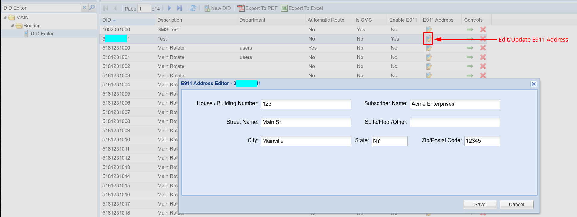
It's a good idea to set the main grid row Description to notate which address is being used, it makes it easier to locate this DID in Step 2
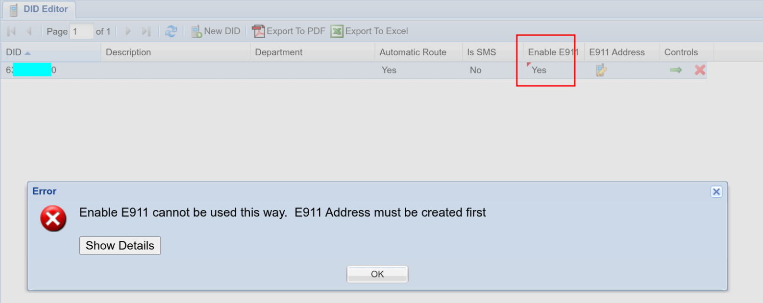
Make sure to set the address as the first step. 'Enable E911' might look to be the place to start, but this field is only for removing E911 from a DID Phone Number.
Step 2 - Associate the E911 DID to the PhoneGroup
Or, create new PhoneGroup for this purpose.
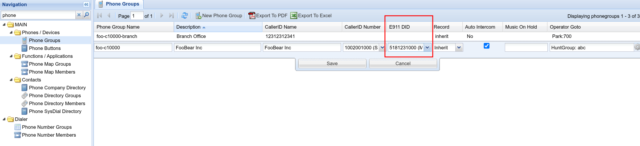
Even if the E911 DID is the same as the CallerID, it still must be selected to ensure correct routing
Step 3 - Associate the Extension/Extensions with the PhoneGroup
Now you're all set!
Keep in mind that placing regular non-emergency calls, will always use 'CallerID' of the Phone Group
And Placing E911 Calls or Testing E911 calls will use the E911 DID and associated E911 Address for these calls
Make sure to dial 933 to validate the setup is correct.
Web Portal Introduction
Row Editor
This page includes specifics on modifying data within the individual screens in the web portal.
Rows
Rows are the individual points of data that you can modify, view, or both. Within rows, there may be various options for editing the data, as well as dynamic or view-only options as well.

Drop Down Menu
When an option has multiple fixed values available, this will typically be displayed as a drop-down menu as shown below. To access the drop simply click on the box itself.
Fill Form
A fill form is a form where you enter the data yourself, depending on the form there may be no restrictions to space and characters, whereas others may require no spaces or special characters.
Checkboxes
Check boxes represent values that are essentially a yes or no (true or false) value. You simply click on the check box to check it or un-check it.
Editing Pre-Existing Entries
If you wish to edit a pre-existing entry within the web portal you simply need to click the row you wish to edit.
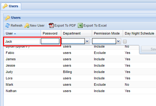
Form Validation
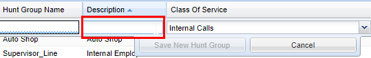
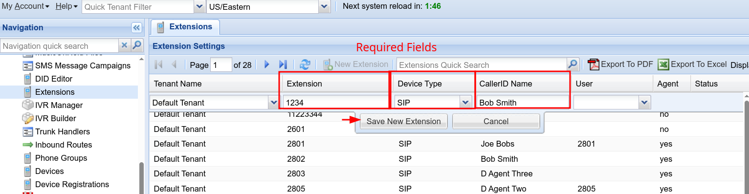
When editing or adding data in forms you will often notice at the bottom of the individual boxes that a squiggle line may span the entirety of the box. In the example below, you will see blue squiggles at the bottom of each box. This indicates that these fields are required.

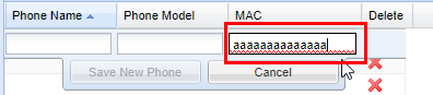
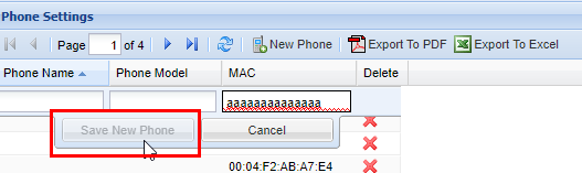
In the following example, you will see red squiggles in the field under the column MAC, this indicates that the entry submitted is invalid, and must be corrected. The web portal will not allow you to save until all fields with a red squiggle are corrected. 
In the example below, you will see a field under the column Description without squiggles, this indicates that the field is optional and does not require an entry.
Since the MAC field is not valid, the web portal is smart and will not allow you to save data. The same goes for mandatory fields that have a blue squiggle underlining them. This is to prevent the saving of any invalid data that could potentially cause a system to not function properly.
Deleting data
Generally speaking in almost all parts of the web portal you have the ability to delete individual data/records by clicking on a red X located on the far right-hand side of a screen (you may have to scroll) in an action column.
Whenever you delete data, a pop-up will appear graying out the web portal behind giving you the option to confirm, You will always see the option of OK, which will delete the entry and then save (followed by the Save Changes message), or Cancel, which will remove the pop-up and not change anything. It can always be assumed by clicking OK you are removing the data in question permanently, so when wondering about what things should be removed, contact your system administrator.
After clicking "OK", your data is permanently deleted.
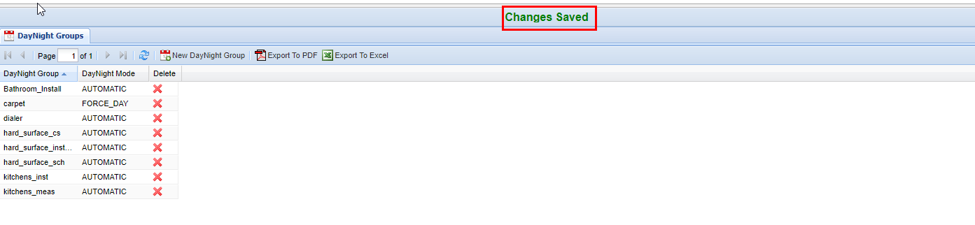
Saving Data
Anytime you complete an action such as inserting, updating, or deleting records, a green confirmation saying Changes Saved will always show if the settings have been saved successfully. This confirmation appears at the top center of the IntellaSoft Web Portal. If it doesn't display after a modification, double-check for errors and if you still have difficulties, consult with this documentation or lastly your system administrator for proper escalation.

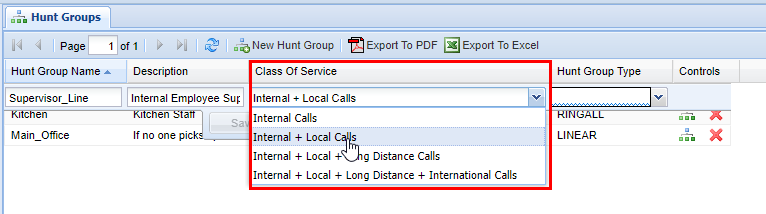
Class of Service
Throughout the web portal, you will see certain screens have a class of service value that must be selected. The class of service can be thought of as a security feature. Currently, the following screens have this value:
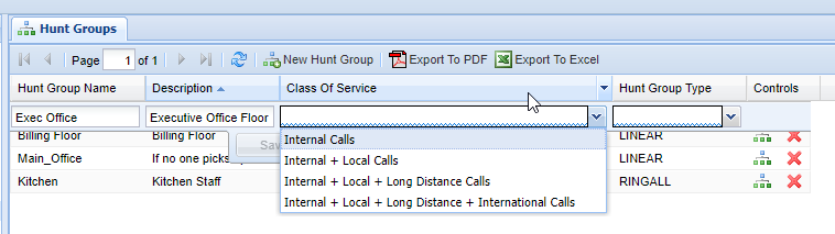

A Class of Service defines what numbers an associated group can call. It is possible to set up specific classes of service to handle specific numbers. By default, most Intellasoft installations will come with 4 default classes of service.
| Class of Service |
Description |
| Internal Calls | Can call internal extensions only. |
| Internal + Local Calls | Same as above but can additionally call numbers with a local area code. |
| Internal + Local + Long Distance Calls | Same as above but can additionally call numbers that are long distance (non-local area code). |
| International + Local + Long Distance + International Calls | Same as above but can additionally call numbers that are internationally based. |
Additional options are available for creating classes of services, but you will need to contact your system administrator/IntellaSoft representative for options on configuring this. It is important to note that the class of service applies to calls that are being transferred from the extension/group that the class of service applies to. There are also options for blocking certain calls at the forefront without them gaining access to the phone system such as the IVR (Interactive Voice Response), live agents, individual extensions, etc.
Overview
This section covers the core basics of the web portal. If this is your first time using the web portal, start by getting familiar with logging in, basic navigation and account management in the Top Level Interface Components section. Afterward, familiarize yourself with the Grid Components layout/editing capability and, lastly, how to change data using the Row Editor.
Pages within the Web Portal Introduction:
- Top Level Interface Components - This section includes the absolute minimums of the web portal. You can start by navigating to your organization's URL. This web address will be given to you by your company's system administrator or an Intellasoft representative.
- Grid Components - Grids contain web portal components for modifying existing data or adding new company-specific information. Although the exact information displayed in web portal examples will vary from your displayed screen, the general technique for adding/changing information will still be covered in this documentation's respective screen pages.
- Row Editor - Modify data within any displayed row on the web portal by using standard widgets.
- Class of Service - Outgoing call permissions can be assigned for hunt groups, extensions, and phone map groups using the web portal screens.
Documentation Formatting
For the purposes of this handbook anytime a specific feature (such as a button, tab, screen, module, etc.) is specified in the guide it will be in a capitalized Bold Face. The red boxes outlining anything within the web portal indicate areas of attention.
Overview Components
Overview
This section includes the absolute minimums of the web portal. You can start by navigating to your organization's URL which will be given to you by your system administrator or Intellasoft representative. Afterwards you will see a login screen. Start by following the instructions below to get familiar with the platform.
Logging In

Top Level Interface Components

 |
 |
| Top bar | The account management bar along the top of the window is used to change your password or logout. |
| Left panel | The navigation panel at the left of the screen is for navigating to different screens within the web portal. |
| Right panel | The content area, filling the majority of the window, will display information and tools based on the selected screen. |
My Account

To change the account password, click on the My Account menu located at the top left corner. Next click the Change password for my account: <username> button.
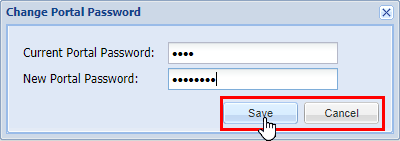
Within the popup, enter your Current Portal Password and New Portal Password. Click Save and there will be a confirmation of Success - Saved password or Invalid current password if the current portal password is incorrect. Click OK to continue.
Logout
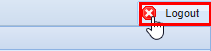
Closing the browser is not enough to be logged out since the Intellasoft Web Portal uses cookies. Remaining idle for an extended period of time may not do the trick either, depending on the specific timeout settings. The best way to logout is to use the Logout button in the upper right-hand corner.
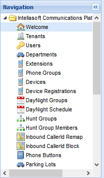
Navigation
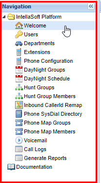
The red box panel on the left is the Navigation. From here you are able to select the various Screens (also called Modules) within the IntellaSoft platform. To select a specific Screen, click on the name you want to access. The subtle difference between Screen and Module is that the screen is the visual component of the exact module on the server. Note that a module may provide features across multiple screens. Anytime the documentation refers to navigating to a screen or module refer to the navigation panel and click the screens' respective name. You will see it highlighted in blue indicating which screen you are currently in.
Screen Content Area

The red box panel on the right is the Screen Content Area which is a Tab Panel. The title of the Screen will be in the tab name.
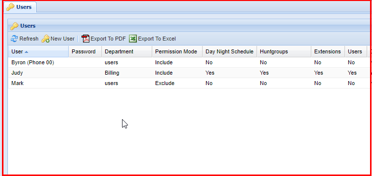
Screens
In this example, we have selected the Users Screen. Notice that Users is highlighted within the Navigation Panel. The Screen Content Area now contains the specific Panels for the screen. In this case, the four smaller Panels are all Grid Panels.
Panel Sizer Bar
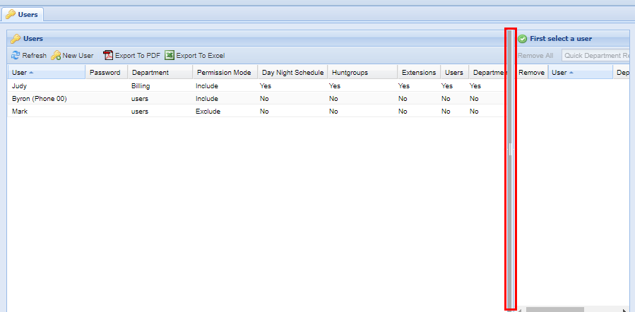
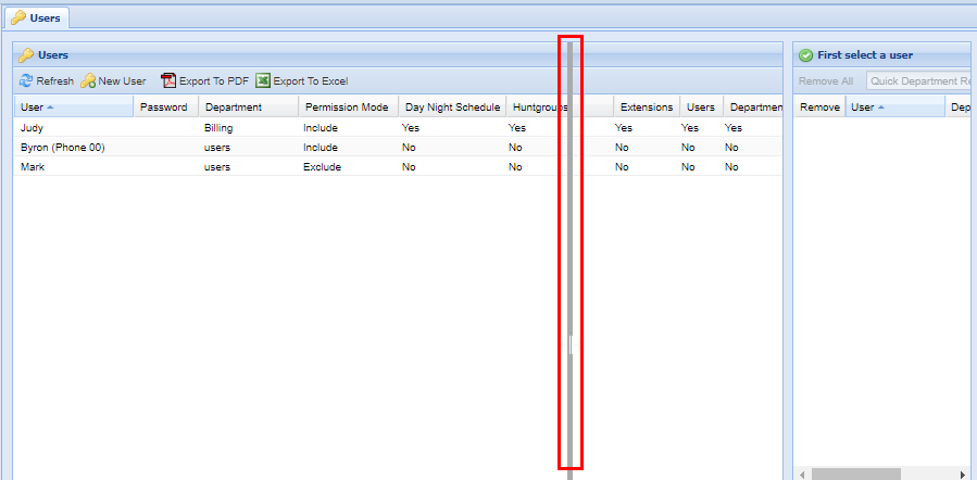
You have the option to resize individual panels within each screen. To do this simply click on the in-between space between panels and drag in the direction to want to resize. Afterwards the panel will be extended right, the opposite works when trying to resize panels to a smaller amount. You can also do this to the height of panels as well.


Panel Tools

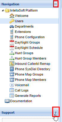
Currently, there are not very many Panel Tools implemented, but an example of a Panel Tool is the option to collapse or expand panels, to provide a better view of other Panels. See the example above.
Group Selection
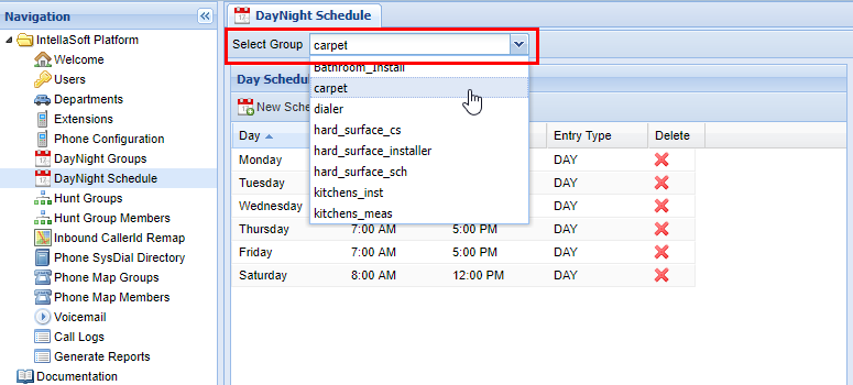
When using some screens such as DayNight Schedule or even Voicemail it is important to note that you have chosen the correct group to modify. This can be done with the Select XXXX (XXXX will depend on the exact screen you are in) function which is located at the top left-hand of the screen.
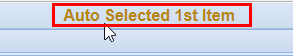
If you are selecting this screen for the first time since logging in, you will also see a brief message such as the one below indicating that it has auto-selected the 1st group that would be included in the drop-down menu for Select XXXX. This is simply to bring attention to the fact that you may have to change the group to modify the one in question.
Grid Components
Overview
Grids contain the components within the web portal necessary for modifying existing or new data, as well as more specific functionality of the individual screens within the web portal. It is important that the exact setup will vary screen by screen, but are still covered in this documentation's respective screen pages.
Panel Tools
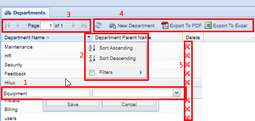
Grids are the main workhorse of the system. This is where you insert, update, and delete Records using (1) Row Editor. Grids allow you to sort and filter using the (2) Column Header Menu and page through lots of data using the (3) Paging Toolbar. Most grids have (4) Grid Toolbar Buttons to perform module commands. Not all columns are sortable or filterable. Some columns have icons which are called (4) Action Columns and have the ability to delete records, or shortcuts to quickly go to an associated screen. These are outlined and numbered in the screenshot below:
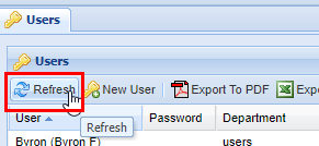
Refresh

| Top bar | The account management bar along the top of the window is used to change your password or logout. |
| Left panel | The navigation panel at the left of the screen is for navigating to different screens within the web portal. |
| Right panel | The content area, filling the majority of the window, will display information and tools based on the selected screen. |
Export to Excel or PDF
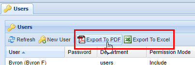
Almost all modules have the option to export the data shown to a table in PDF file format, or an Excel spreadsheet. Either click on Export to PDF or Export to Excel and it will start the download process. Depending on the browser settings, there may be a prompt to choose a location or it may download to a default destination such as the "downloads" folder. Consult the browser's documentation for more information.
Examples of data exports: PDF or Excel Spreadsheet.
Module Specific Buttons
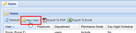
Almost all modules have buttons that are specific to their function. Such as the example below; the New User button is specific to the Users module.
Page Options
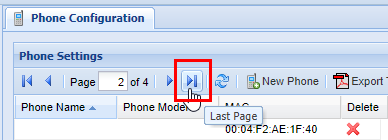
When dealing with large quantities of data, the platform automatically splits the entries into pages that can easily be navigated from the toolbar. In this example below, the page is on page 1 of the 4 possible pages available.
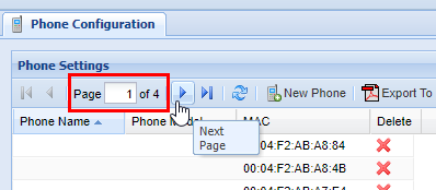
To move forward one page click the arrow to the right (If you hover over it, a tool-tip will pop up stating "Next Page.")
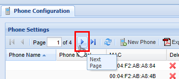
You can also skip to the last page by clicking the arrow to the right of the first arrow.
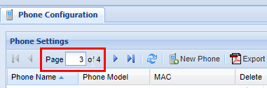
You can also move from page to page by simply typing the desired page number into the page indicator. 
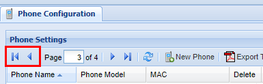
Similar to moving forward one page and moving to the last page, you can conversely move back one page, or move to the first page.
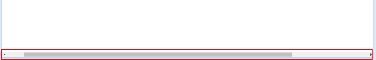
Scroll Bar
In some cases, it is necessary to use the scroll bar on the bottom of the page to navigate to the left or right to access certain settings within the Grids. Click and drag the bar to the left or right until you find the settings you wish to modify.
Additional Columns
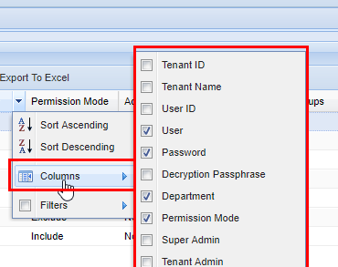
Filter Function
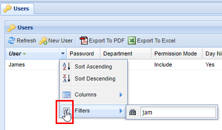
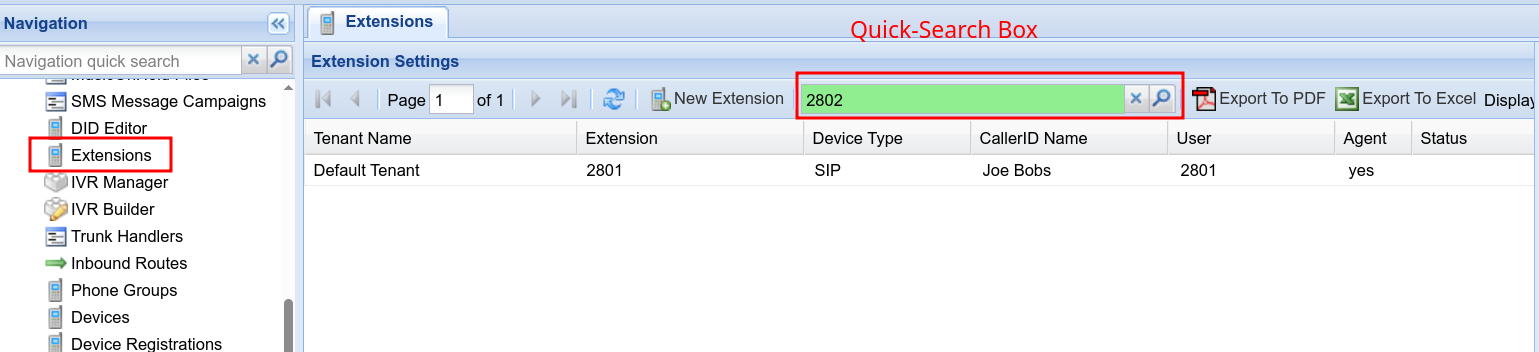
Filters are a powerful method of sorting through a lot of data. Not every screen has lots of data, but on screens that do filtering is extremely useful. You can apply filters to multiple columns at once. Start by accessing the column header menu and click the Filters item. A pop-up will appear with a small pair of binoculars. Type your filter. Keep in mind that each filter is applied to each item individually. As you type, the grid will start to populate with data that the filter has found. 
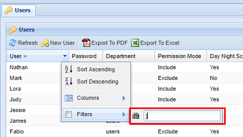
When finished, press enter or click out of the filter box.
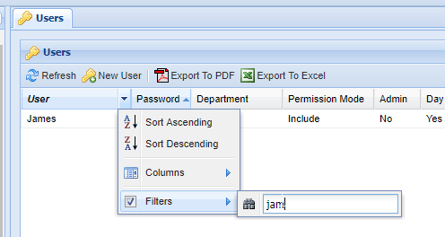
By typing "jam", the server finds the User named James. Columns that have an active filter on them will always be bold and italicized as shown below.
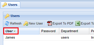
To deactivate the filter, click the column's header menu and then click the checkbox next to the filter option. Another option is to delete the text in the filter box. After you have done this, any filtered-out data will reappear:
Not all columns are text forms, some give the option such as yes or no as checkboxes:
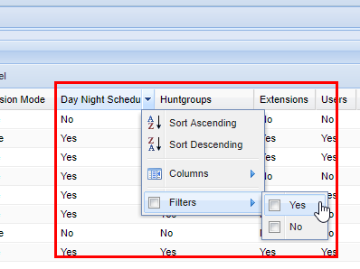
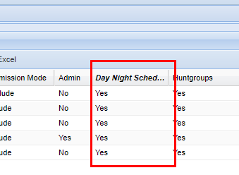
After checking yes for the filter column option, the grid will show all the rows where yes has been selected. The column's name becomes bold and italicized to indicate that a filter is active.
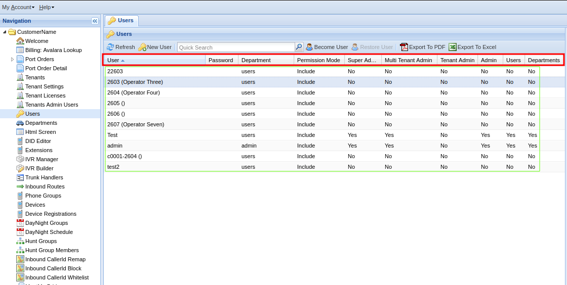
Users
The Users screen is for managing people who will have access to the IntellaSoft Web Portal to make changes to the phone system, delegate permissions, or other functions such as accessing call logs and voicemail. When a new user account is added, by default that user will be able to log in and see their own voicemail. It is up to the manager who is creating the account to check / un-check the specific permissions for what screens that user should have access to. A very important aspect is the delegation of what users a user can control via the Permission Mode setting with Include or Exclude mode (more on this below).
Video Tutorial -- Please watch Full Screen
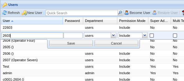
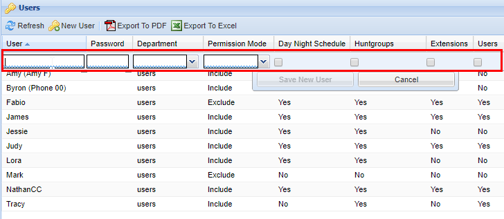
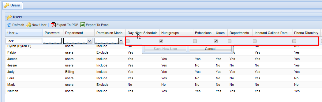
Adding a New User
2) Click the New User button.
3) The following fields are required when creating a new User.
| Field |
Type |
Description |
| User | Text | This will be the username for logging into the portal. |
| Password | Text | For logging into the web portal |
| Department | List | Select a department the user will be in |
| Permission Mode | List | Either exclude or include as described below |
4) Fill in User, Password, and Department.
5) Then set Permission Mode to Include or Exclude. (Explained below)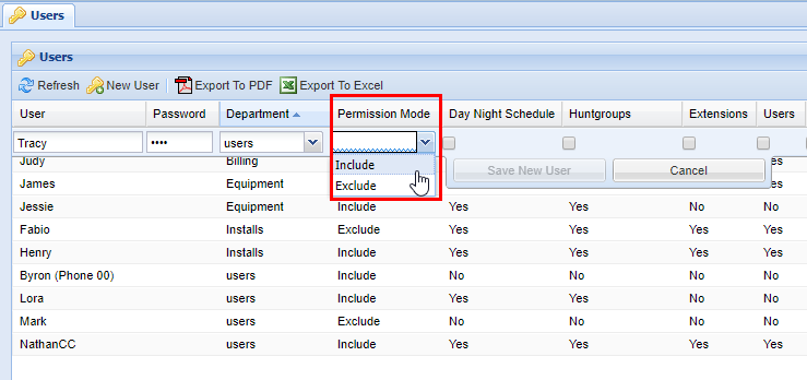
Permission Mode Include: By default, the user will not have access to any other users. Allowed users will be determined by which ones are Included.
For example, use this mode when setting up a manager of a small department. The manager may need access to users Abby, Bob, and Chris. These users would be added as Included Users
Permission Mode Exclude: By default, the user will automatically have access to ALL USERS. Hidden users will be determined by which ones are Excluded.
For example, use this mode when setting up an admin that needs access to the entire system except for the calls and voicemails of the President and Vice President. The President and Vice President would then be added as Excluded Use
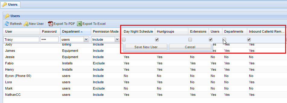
6) After selecting the permission mode, select the appropriate Permissions the user will have access to. You will need to use the scroll bar located at the bottom of the users table to view additional permissions. Permissions are on a Per-Screen basis.
For example, if a supervisor account was needed that could only view the call history of the system in Call Logs.
- Make sure that the 'Admin' permission is unchecked
- Make sure that ALL other permissions are unchecked
- Make sure that 'Call Logs' is checked
This user will now only have access to view the Call Logs screen.
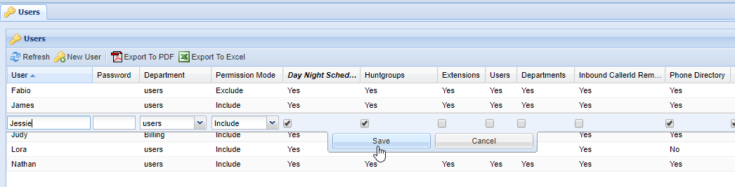
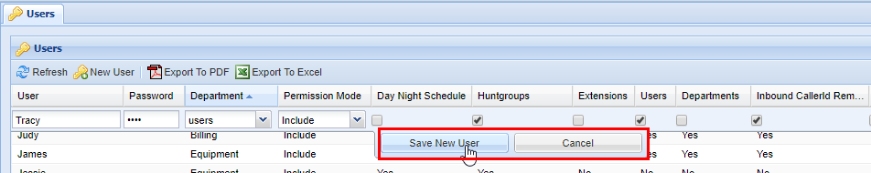
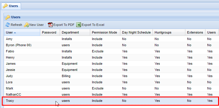
7) After you have confirmed that all the options for the new user are correct, save by clicking on Save New User, or cancel if applicable. Afterwards, a green message will appear stating Changes Saved.
Removing a User
2) From the Users tab, select the correct User you wish to delete. The user you selected will be highlighted in blue, as shown below.
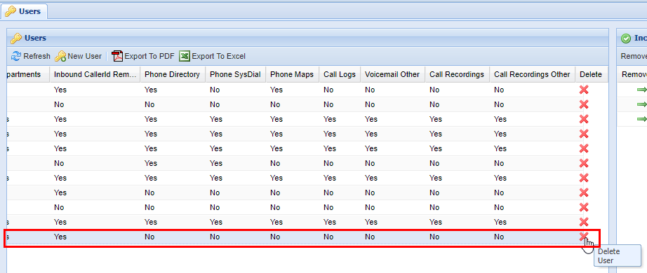
4) A confirmation pop-up will appear confirming your selection. If you wish to delete, click OK. You will see a message stating Changes Saved. If this is not the entry you wish to delete click Cancel.
Including/Excluding Users
For this example, we will use a User that has their permission mode to Include. This means that by default, the User will not have access to any other Users and you must manually include Users. (On the other hand, Users set with an Exclude permission mode will have access to all Users if no users are added to the exclude list.)
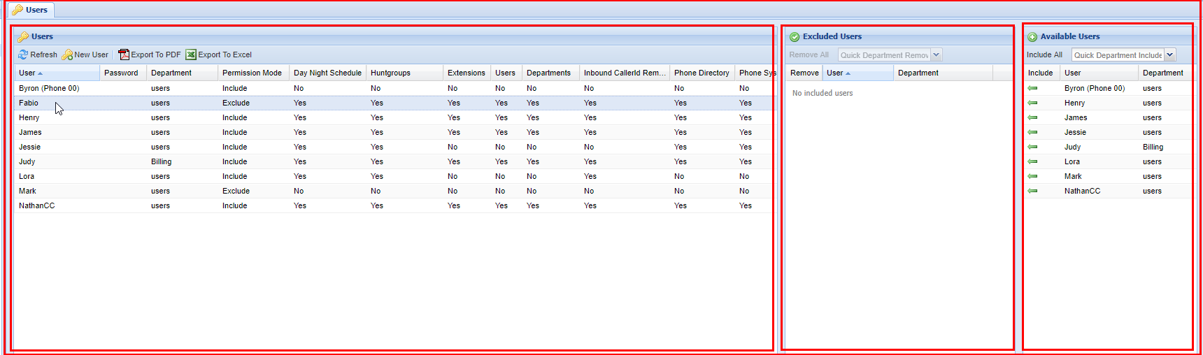
Select a User to start adding other users to their Exclude or Include list (permission dependent). The User you are currently adding users for will have its row highlighted like the example below.
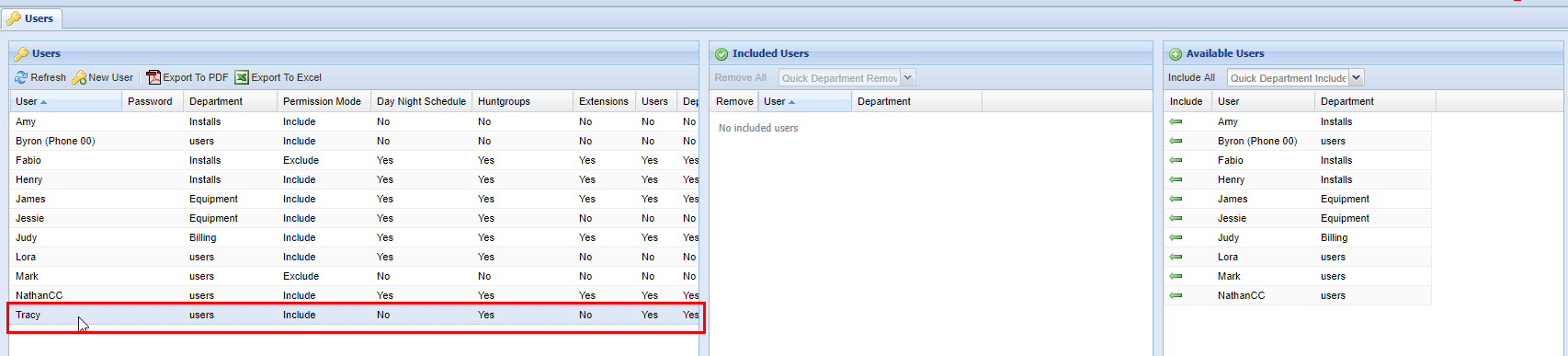

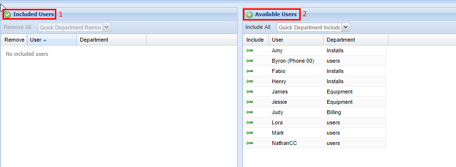
There are two endpoints before we add any users. In addition to the Users panel, there is also the Include/Excluded Users panel (see "1" below. Again this is dependent on what the Permission Mode mode for this particular user is set, if it's an Exclude the text would say Excluded Users as opposed to Included Users) which shows all the users that have been added to the Included/Excluded User list) and the Available Users (shown are all users that can be added to Excluded/Included User list). Again it's important to note that in this particular example, the User Tracy has a Permission Mode set to Include, so these available users are the ones she does NOT have access to.

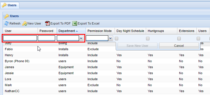
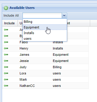
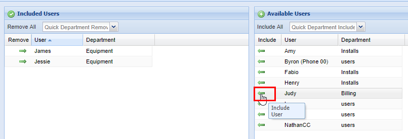
There are three options for adding users to list. You can select the Include All Button (1, adds all the available to users to the list), Green Arrow in the Include Column (2, adds each User to the list individually) or using the Quick Department Include (3, or Exclude, if applicable). For the purposes we are going to add users using the Quick Department Include function. To do this simply click on the drop down menu and a list of the available Departments will appear. This will add Users based on their department and who is available to add in the Available Users list.
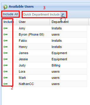
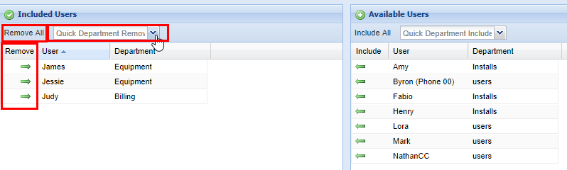
As you can see by the example all Users in the Equipment department were added to the available user list. You can also go through and add Users individually too, or include them all if applicable.

Removing Users from an Include/Exclude Users list works in the opposite way of adding them to list from the Available Users list. You are able to remove them individually via the right pointing green arrow, remove all at once, or remove by department (the same way you can from the Available User list).
Including/Excluding Phone Numbers
You can also grant permissions to a User on a per-phone number basis, allowing them to see call records for users they are not otherwise allowed to modify.
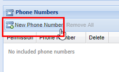
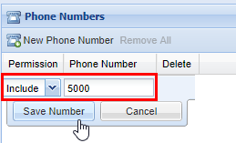
2) While in the Phone Numbers panel click the button labeled New Phone Number, a row editor will appear in the grid below.
Enter a permission type from the drop-down based on the phone number you are going to include or exclude for this user. Afterwards, enter a phone number. This can range from an internal extension to an outside long-distance phone number. When you are satisfied click the Save New Number button, after you will see a message stating Changes Saved.
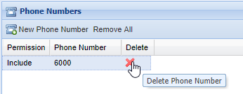
If you need to remove a member, locate the Phone Numbers panel after you've selected the User you wish to modify, and click the red X in the Delete column. A confirmation pop-up will appear confirming your selection. If you wish to delete, click OK. You will see a message stating Changes Saved. If this is not the entry to wish to delete, click Cancel.
Departments
On the Departments screen, you can associate Users with Departments. On other screens, you can quickly add all Users in a Department to a list, making updating permissions much faster, especially for large Departments.
Adding a New Department
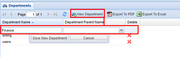
2) Click the New Department button and enter a name for the department.
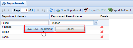
3) If you are creating a Department under another Department, effectively creating a Department Hierarchy) select one from the drop-down under Department Parent Name.
4) When you are finished, click Save New Department. After you click save you will see a message stating Changes Saved.
Department Hierarchy
As stated above you can have Departments within Departments.
2) Create a new department, following the steps above, then click the drop-down menu labeled Department Parent Name, and select a Department to place the department under.
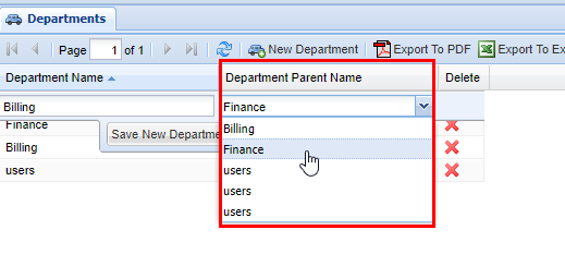
3) When you are finished save the Department by clicking on the Save New Department button, afterwards you will see a message stating Changes Saved.
Deleting a Department
2) Find the Department you want to delete and click the red X in the Delete column. A confirmation pop-up will appear confirming your selection. If you wish to delete, click OK. You will see a message stating Changes Saved, if this is not the entry to wish to delete click Cancel.
Note: To remove a Department, you will also need to delete any users assigned to the department or reassign the Users department to another department.
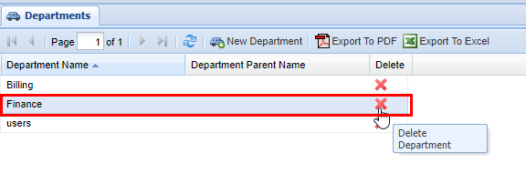
3) If you see an error such as the one below when attempting to remove a Department this means that there is still a User that is associated with a Department. To remove a Department, you will also need to delete any users assigned to the department or reassign the Users department to another department.


Extensions
IntellaPhone Setup Instructions
First: Choose Extension or Create New
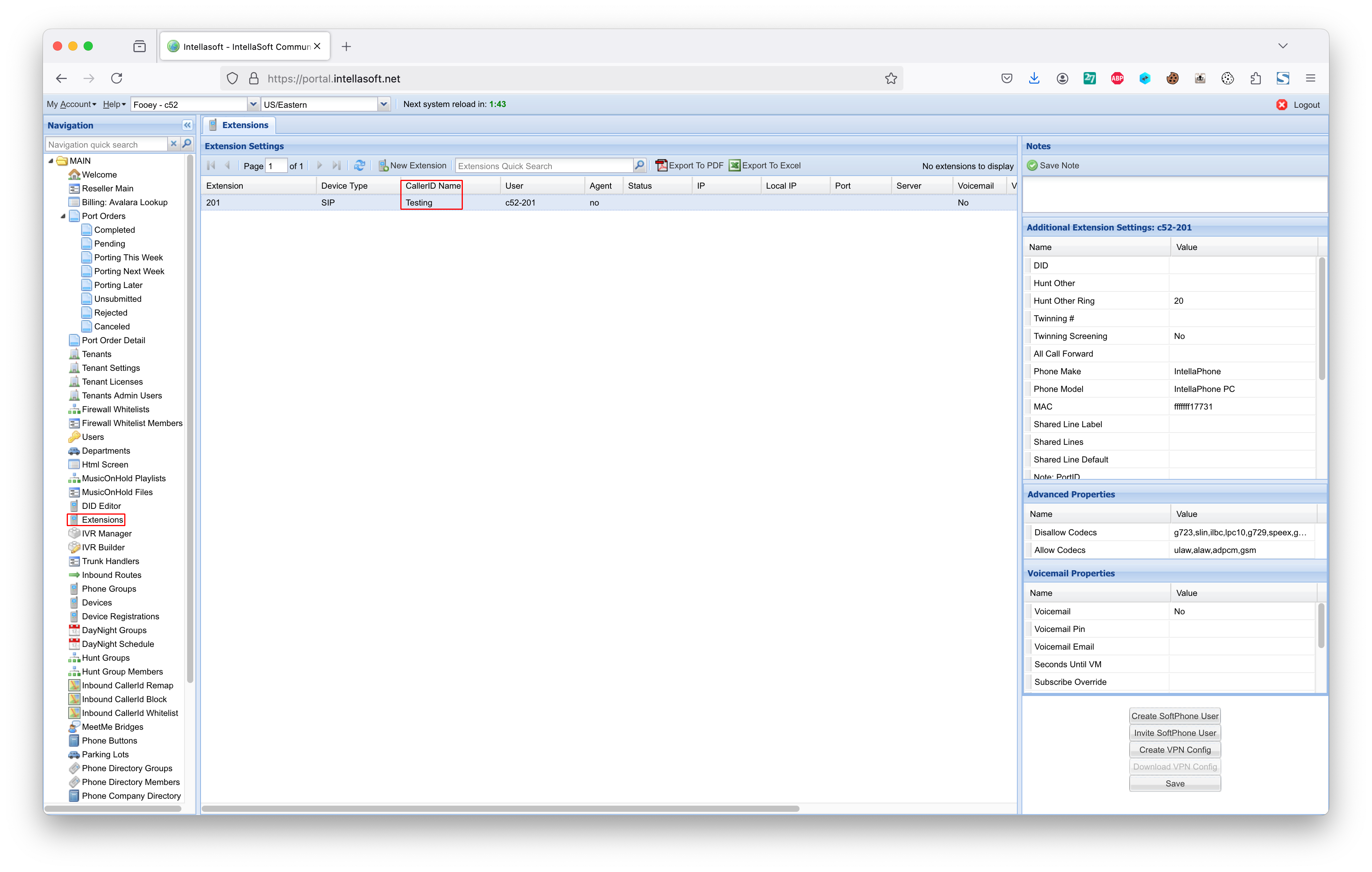
1) Locate Extensions, and then find the Extension to set as a SoftPhone
or
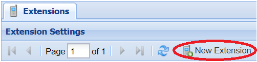
2) Use the 'New Extension' button
Locate
Create New
Next: Set CallerID Name and Phone Make/Model
1) Set CallerID name
2) Enable Voicemail (optional)
3) Set Email Address (optional, for voicemail)
4) Set Phone Make: IntellaPhone
5) Set Phone Model: IntellaPhone PC
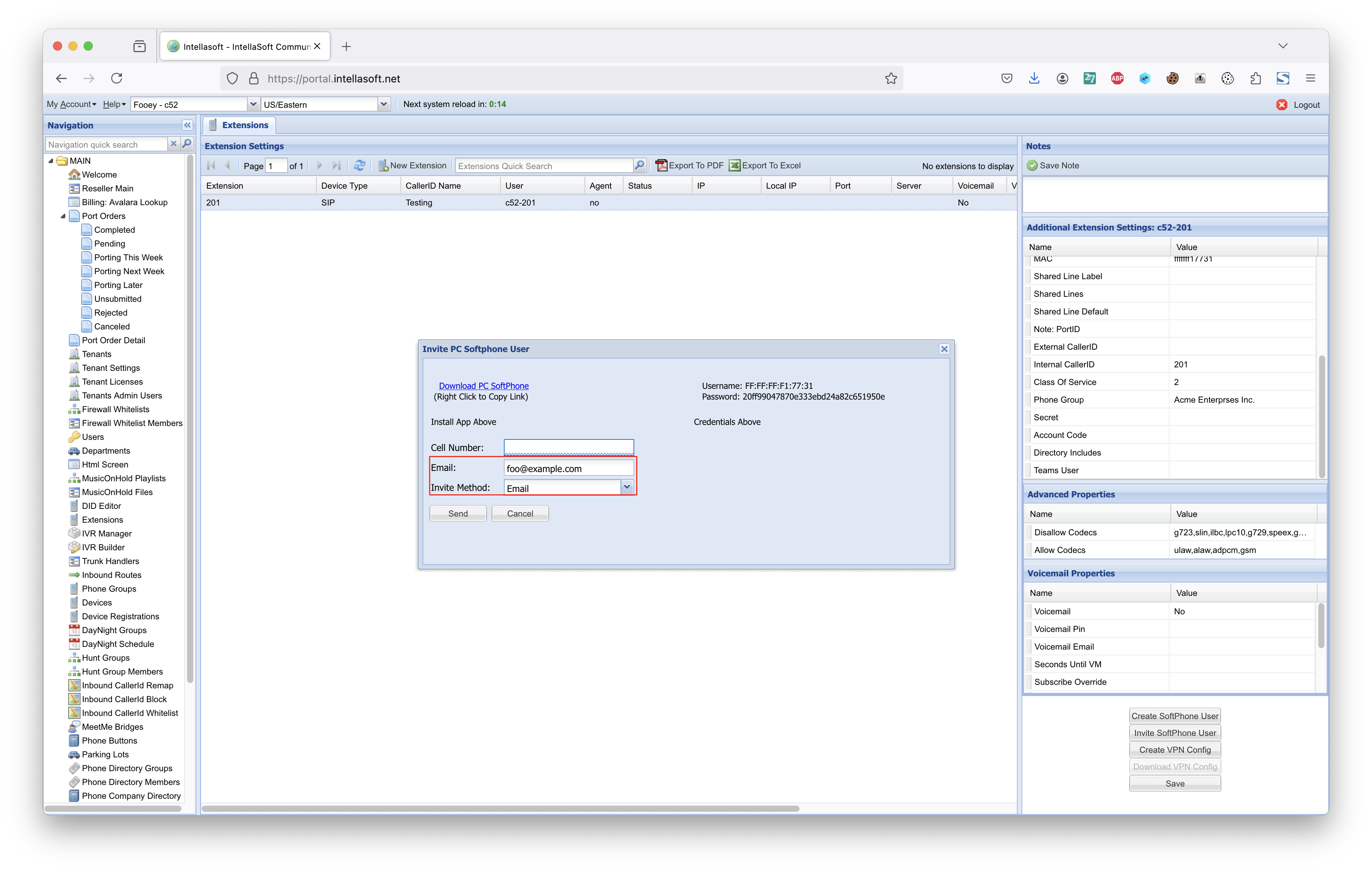
Second Step: Send the Invitation Email
Third Step: Wait for Email to be Sent. This may take 30 seconds or more.
Fourth Step:The user will receive an email that looks like the following
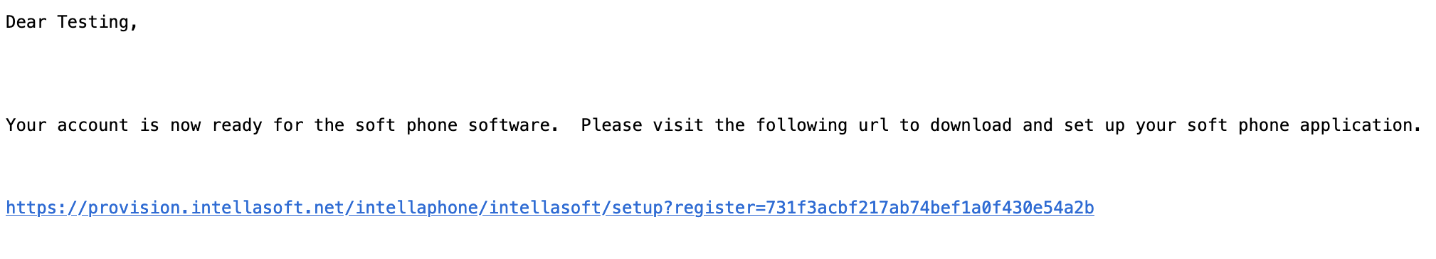
The above link is purely an example. It is important to use the exact link that was sent in the email in order to proceed to the next step.
Fifth Step: The user will visit the URL in the email and install the application
Once installed, the user will then copy and paste the Username and Password into the matching fields of the application logon

1) Download and install the IntellaPhone Application
2) Once installed, copy the Username from this web page into the Username field of the Account Box
3) Followed by, copy the Password from this web page into the Password field of the Account Box
4) Leave 'Remember Details' checked
Extensions (Archive)
The Extensions screen allows you to associate Extensions with phones. A phone must have an Extension associated with them to receive calls. Extensions can be associated with physical phones, soft phones, or voicemail boxes.
Adding an Extension
| Field |
Type |
Description |
|
| Required | Extension | Numeric | Extension number |
| Device Type | List | Type of Device the extension will be associated with | |
| CallerID Name | Field | Caller ID name, this may be overwritten depending on system settings | |
| Optional | User | List | Portal users to be associated with this extension |
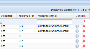
| Voicemail | Checkbox | Enables or disables voicemail | |
| Voicemail Pin | Numeric | Pin number to access voicemail, will only show if voicemail has been enabled. | |
| View Only | Agent (further explained below) | Value | Yes/ no value, states whether or not this extension is associated with an Agent (part of the IntellaQueue/call center settings) |
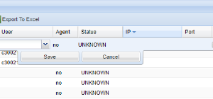
| Status (further explained below) | Value | Status of device registered to server. | |
| IP (further explained below) | Numeric | Internet Protocol address of the extension. | |
| Port (further explained below) | Numeric | Protocol port that the extension residents on |
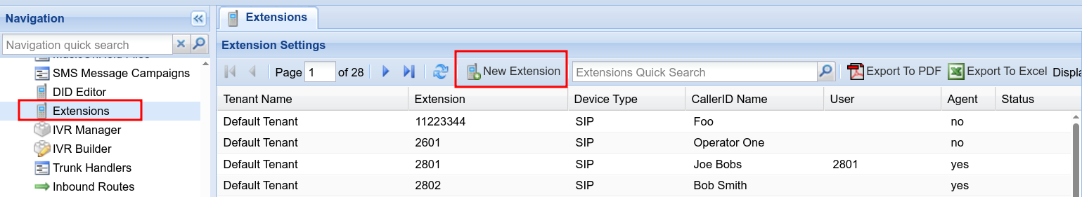
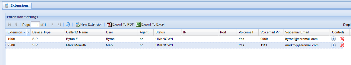
Start by navigating to the Extensions screen via the Navigation Panel. Next click New Extension button. A row editor will appear in the grid below.
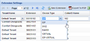

The following options will be dependent on your organizations needs, so it is important to consult with your system administrator during your initial setup of your IntellaSoft web portal, or making any changes thereafter. Start by adding an appropriate Extension number, afterwards select the type of device you are creating the extension form. Several options are available from the drop down men.
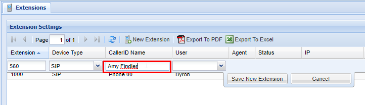
Afterwards, select a CallerID Name, this is what will appear when this extension attempts to call others within the organization.

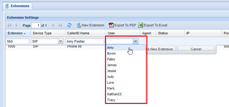
SITUATION DEPENDENT: If the Extension you are adding will also have a User that requires permission access (see Users page for more information on configuring users), select the appropriate User from the drop down menu. If this does not apply skip to step 6.

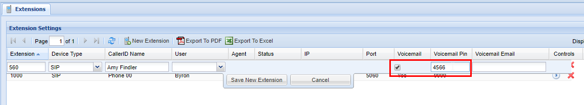
At this point, you will also have the option to setup a voicemail for the Extension. If the extension does not require a voicemail go ahead and click Save New Extension (if you go ahead and save you will see a message stating Changes Saved); otherwise move on to step 7. To enable voicemail, click the checkbox in the Voicemail column, afterwards select a numerical PIN for the voicemail, we recommenced something memorable between 4-8 digits.

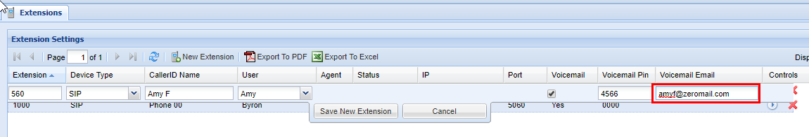
Next, you also have the option to have voicemail notifications and recording sent to email, in the following box simply input the desired email address that voicemail recordings and notifications can be sent to. Important: Ensure that the email address you have inserted is correct.

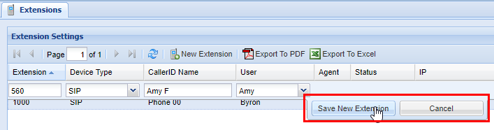
Lastly; review all of the information submitted from Extension Number to Voicemail Email, once you have ensured all of the data is correct and accurate click Save New Extension. Afterwards you will see a message stating Changes Saved.

There are several important limitations to keep in mind regarding Extension.
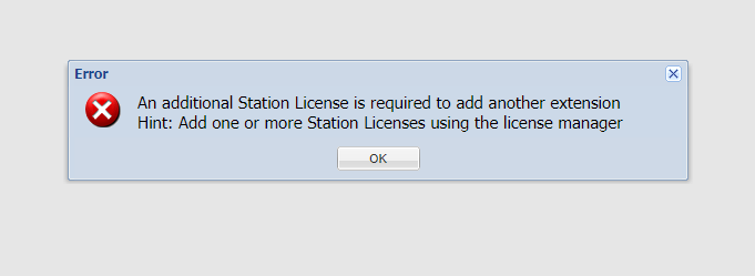
Firstly, the number of Extensions depends on the licensing of your IntellaSoft web portal. Depending on the number purchased during your initial setup of your IntellaSoft system you may need to be purchase additional licenses to gain access to more extensions. We are working on a way to make this process seamless, but for now you will need contact your IntellaSoft Sales representative who will be more than happy to assist you during that process. If you see an error such as the one below, this means you have reached the maximum number of Extensions your licenses allow for.

Next, you may have noticed 4 columns with information that you cannot edit. This is simply information that the IntellaSoft web portal is reading from the server, and are explained below.
Agent: In this column it will simply state Yes or No. Agents are are specific the Call Center options of IntellaSoft Web Portal. This information is helpful in large organizations with multiple departments including ones that have a dedicated call center with live Agents, whether or not an Extension is identified as an agent depends on your licensing configuration and organizations needs. If you are needing add a call center to your IntellaSoft Communications Platform, contact your IntellaSoft representative to discuss options.
Status: See the table below
| Status |
Definition |
| OK | The end-point is registered and properly running on the server (you should see an IP and Port associated with the extension). An end-point can represent a physical phone, software phone, PA speaker, as well numerous other physical or virtual communication devices. |
| UNREACHABLE | The system cannot reach the phone, but the phone has been registered prior. This usually indicates that there may be an issue. Contact your system administrator for assistance. |
| UNKNOWN | This will be the status of the endpoint when it was previously UNREACHABLE, and the system has given up trying to contact the endpoint. |
| UNMONITORED | This means that the endpoint has intentionally been set so it does not monitor status. The IP and PORT will only be populated if these are configured. Despite being Unmonitored, the endpoint can still be called. When this endpoint is called, the system will try to reach it until the system defined timeout is reached. If the endpoint is unresponsive at the time of the call, the call will fail. |
| BLANK | No phone has been registered to this extension. There could be several reasons for this, the phone could simply not be plugged in or programmed to this extension. The Contact your system administrator if you suspect a problem. |
IP: This columns refers to the IP (or Internet Protocol) Address that the extensions lies on. This information is automatically updated based on the current server information. Generally speaking this is utilized by IntellaSoft staff, your organizations IT or System Administration to diagnose potential problems, should they arise. If you have questions regarding this, please direct them to your System Administrator. IP of the phone itself
Port: Port that the phone resides on.

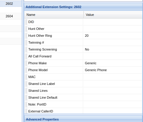
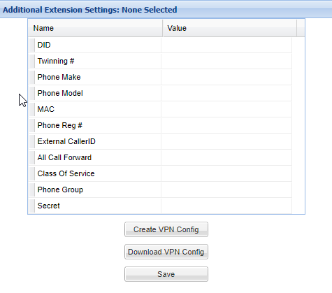
Additional Extension Settings
Extensions may have to have additional information about them, this will depend on your organizations needs. Contact your system administrator for more information.
| Name |
Definition |
| DID | Inbound DID |
| Twinning # |
Twinning number. Ring an external number such as a cell phone. |
| Phone make | Make of the phone in question |
| Phone Model | Model of the phone in question |
| MAC | MAC address of the phone, if registered to a physical phone |
| Phone Reg # | Registration number on the physical phone (ie: polycom reg number) |
| External CallerID |
What callerid to use when the extension dials out a route |
| All Call Forward |
Call forwarding |
| Class of Service | Class of service when this extension makes a call |
| Phone Group | Phonegroup that this extension is a member of |
| Secet | Secret password to use for incoming and outgoing requests, unless overridden using 'auth' |
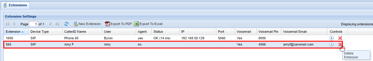
Removing an Extension
Warning
Caution should always be exercised when removing an Extension. Even if an extension is not physically used and thought to be inactive, or it is not connected -- the associated voicemail box might be being used elsewhere in the system, or the extension may have a [Call Forward] in place. Ensure that it is verified that all functions related to this extension are unused or unneeded before removing.
A confirmation pop up will appear confirming your selection. If you wish to delete click OK, you will see a message stating Changes Saved, if this is not the entry to wish to delete click Cancel, to return to the screen.
Overview
An extension is an assignment to a physical phone, softphone, voicemail box, or any similar device configured within the system. A phone must have an extension assigned to it to receive calls.
A user cannot configure his or her extension. Only an administrator can update an extension.
Configuration Options
| Field |
Type |
Description |
Required |
||||||||||||
| Extension | Alphanumeric |
Extension identifier
Numeric digits are recommended if the extension must be dialed from a phone. |
Yes |
||||||||||||
| Device Type | List |
Extension device type
VIRTUAL and SIP-VIRTUAL device types do not use extension licenses |
Yes |
||||||||||||
| CallerID Name | Field |
Caller ID name – displayed on devices that support caller ID |
Yes | ||||||||||||
| User | List |
The portal user associated with the extension (refer to Users for more information) – select if a specific user requires permission to access
VIRTUAL and SIP-VIRTUAL device types do not use extension licenses. |
Yes |
||||||||||||
| Agent | Value |
Indicates if the extension is associated with an agent |
Read-only | ||||||||||||
| Status |
Value |
Status of the device registered to the server
|
Read-only |
||||||||||||
| IP | Numeric |
Internet protocol address (IPv4 format – e.g. 255.255.255.255) assigned to the extension |
Read-only | ||||||||||||
| Port | Numeric |
Device signaling port |
Read-only | ||||||||||||
| Voicemail | Checkbox | Enables or disables voicemail | No | ||||||||||||
| Voicemail Pin | Numeric |
Voicemail PIN – enabled if voicemail is enabled |
Yes if voicemail is enabled | ||||||||||||
| Voicemail Email |
Email address where voicemail messages are sent – enabled if voicemail is enabled |
No | |||||||||||||
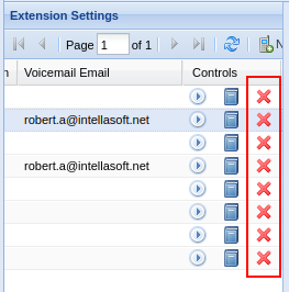
| Controls |
n/a |
Extension tools
|
n/a |


Additional Configuration
Some extensions require additional configuration, depending on your organizational needs. These configuration options are described under Phone Configuration. Contact your system administrator for more information.
Adding an Extension
1) Click Extensions on the Navigation pane. The Extension Settings pane appears.
2) Click New Extension on the upper menu.
3) Enter the fields as required. Refer to Configuration Options above.
4) Click Save New Extension.
The new extension has been added.
Editing an Extension
1) Click Extensions on the Navigation pane. The Extension Settings pane appears.
2) Double-click the extension row you want to edit. You should see a row editor.
3) Make any desired edits. Refer to Configuration Options above.
4) Click Save.
Deleting an Extension
Warning: Even if an extension is inactive or disconnected, it may have call forwarding enabled, or the associated voicemail box may be used elsewhere. Ensure all functions related to the extension are unused before removing it.
1) Click Extensions on the Navigation pane. The Extension Settings should appear.
2) Under the Controls column, click the red X for the extension you want to delete.
3) Click OK to delete the extension.
Additional Notes
- The number of available extensions depends on your IntellaSoft licensing. You may need to purchase additional licenses to add more extensions. Contact your IntellaSoft sales representative for more information.
Phone Configuration
Overview
The Devices screen is for adding physical phones to the system, removing them from the system, or attaching them to an extension.
The Extensions screen is for managing the properties of individual extensions.
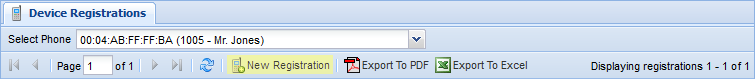
The Device Registrations screen provides configuration options for phones.
The Phone Groups screen (not fully supported) is for creating groups of extensions that share some properties.
Adding and configuring a new phone
1) First, create a new extension on the Extensions screen.
- "Extension" can be any unused extension.
- "Device Type" should usually be SIP.
- "CallerID Name" should be something that identifies the phone.
- All other fields are optional. For more information, see Extensions.
2) Create a new device on the Devices screen.
- "MAC" should be the MAC address of the new phone.
- "Main Extension" should be the extension created in Step 1.
- "Phone Type" is the manufacturer of the phone; either POLYCOM or YEALINK.
- All other fields are optional. For more information, see Devices.

3) Configure the device on the Device Registrations screen.
- For information about the specific fields, see Device Registrations.
Devices
Device Settings
| Name |
Description (What it does) |
Properties (How you interact with it) |
| MAC | The MAC address of a physical phone. | Every device must have a unique, properly formatted MAC address. |
| Main Extension | The device's assigned phone line. A device must have an extension to make or receive calls. | Extensions can be created on the Extensions screen. Two devices cannot have the same extension. |
| Main CallerID | Internal CallerID. This is seen only by phones on the same network. | Auto-filled based on assigned extension. Can be configured on the Extensions screen. |
| Main PhoneGroup Name | The PhoneGroup of the selected extension. Extensions in the same PhoneGroup will have some shared properties. | Auto-filled based on extension. PhoneGroup can created on the Phone Groups screen and assigned on the Extensions screen. |
| Phone Name | A name assigned to the phone. | An optional field used only for bookkeeping. |
| Phone Type | The manufacturer of the phone. | Must be POLYCOM or YEALINK. |
Additional Device Settings
| Name |
Description |
Properties |
| Phone Model | The model number of the phone. | An optional field used only for bookkeeping. |
| NTP Server | The address of the time server used to update this device's clock. | Optional. If blank, a default NTP server will be used. Typically only necessary for off-site phones. |
| Secure Provision | Determines whether this phone encrypts its provisioning information. Turning this on requires additional setup. | Off by default. Typically only necessary for phones using off-site or publicly accessible networks. |
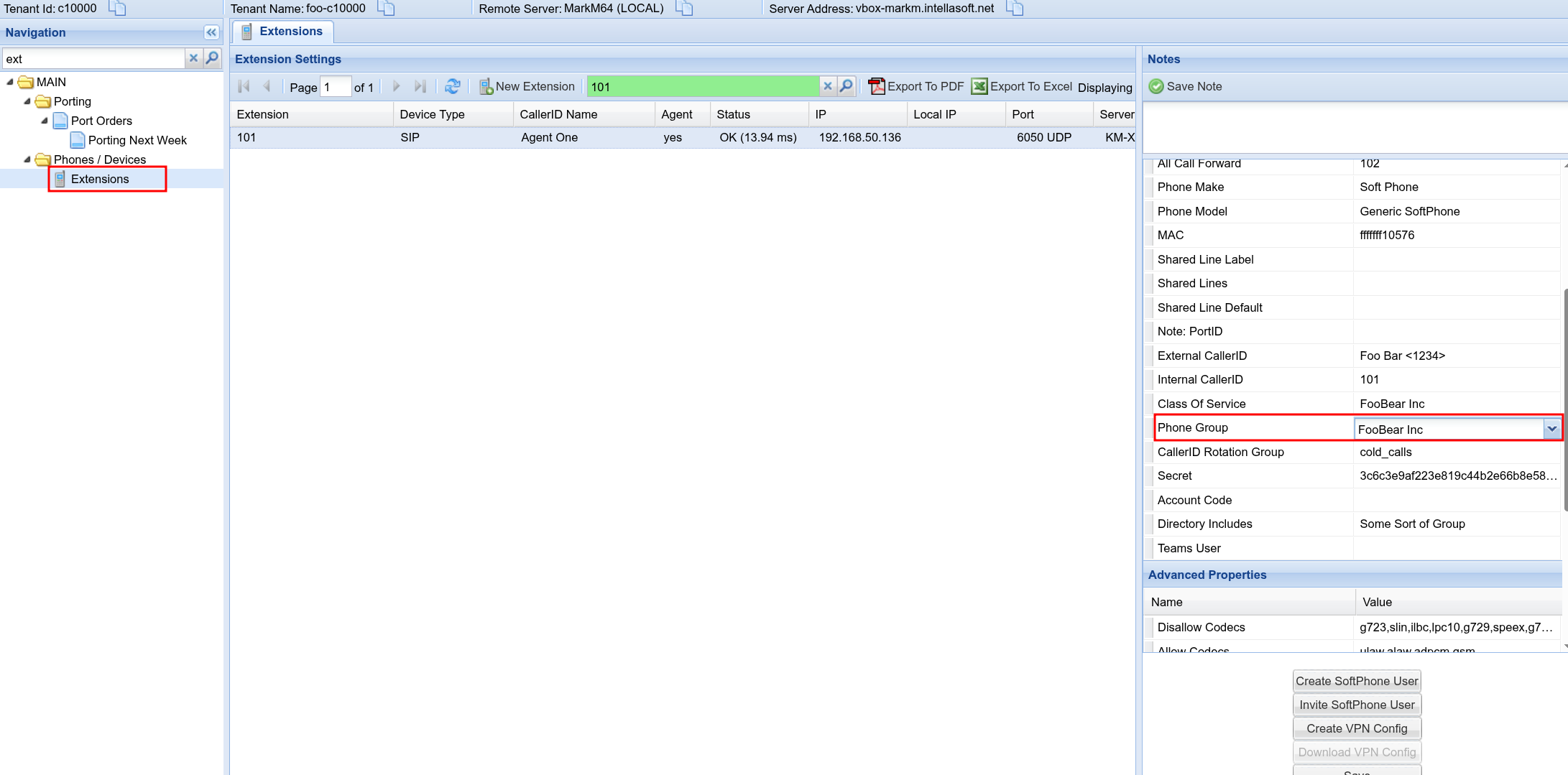
Extensions
The Extensions screen consists of three panels: "Extension Settings", "Additional Extension Settings", and "Notes".
Extension Settings
|
Name |
Description |
Properties |
|
Extension |
An extension. | Must be unique. Can be assigned to a phone on the Devices screen. |
| Device Type | The communication protocol used by this extension. | Once set, this is typically not changed. Usually it should be SIP. IAX2 is used for high volume networks. DAHDI is rarely used. VIRTUAL is used for call forwarding or mailboxes. SIP-VIRTUAL allows one phone to have multiple attached extensions. |
| CallerID Name | The internal CallerID for this extension. Only visible on internal calls (calls between phones registered on the portal). | No technical restrictions. This should be some descriptive identifier, such as the name of the phone's primary user. |
| User | The web portal account assigned to this extension. | Optional. If set, this allows a user-level account to manage their assigned extensions through the web portal. |
| Agent | Shows whether this extension is assigned to a registered Call Center Agent. | Read-only. This is set on the Agent Allocation screen and may not be available on all systems. |
| Status |
OK: this extension is reachable through the network. UNREACHABLE: this extension is not responding to network activity. UNKNOWN: there is no registered associated device. |
Read-only. |
| IP | The network address used by this extension's associated device. | Read-only. This is typically a dynamic address and may change. |
| Port | The network port used by this device. | Read-only. This is assigned by the host and typically not changed. |
| Voicemail | Controls whether or not this extension has a voicemail box. | |
| Voicemail PIN | The password for this extension's voicemail box. | Must be defined if voicemail is enabled. It can be any numeric string and should be at least 3 digits long. |
| Voicemail Email | Voicemail notifications are sent to this email address. | Optional. This should be a working email address. |
Additional Extension Settings
| Name |
Description |
Properties |
| DID | This extension's direct line. | Optional. If provided, this must be a working phone number assigned to your system. |
| Hunt Other | Incoming calls to this extension will simultaneously ring the number listed here, and will be transferred to whichever line first picks up. | Optional. This may be another registered extension, or any external number (such as a cell phone). |
| Twinning # | Incoming calls to this extension, if not picked up, will stop ringing the main extension and instead transfer to the number listed here. | Optional. This may be another registered extension, or any external number (such as a cell phone). |
| Phone Make | The type of phone assigned to this extension. | Rarely used. This should usually be "Generic". Selecting "Soft Phone" populates the "Secret" field, allowing for setup of a simulated soft phone. |
| Phone Model | The assigned phone's model number. | Very rarely used. This should almost always be "Generic Phone". |
| MAC | The assigned phone's MAC address. | Information displayed here for ease of access. The assigned device can be changed here, but should normally be changed on the Devices screen. |
| Phone Reg # | This extension's list placement on the associated device's display. | Information displayed here for ease of access. This is typically "1" for all phones using only a single extension. Phones with multiple extensions should normally be managed on the Device Registrations screen. |
| Shared Line Label | If this extension is configured as a shared line, this will be its default display name. See Shared Lines for more information. | Information displayed here for ease of access. The Phone Buttons screen should be used for all shared line management. Changes made here will not update the Phone Buttons screen, potentially leading to mismatched and broken configurations. |
| Shared Lines | If this extension is configured as a shared line, this will be the maximum allowed number of concurrent calls. See Shared Lines for more information. | Information displayed here for ease of access. The Phone Buttons screen should be used for all shared line management. Changes made here will not update the Phone Buttons screen, potentially leading to mismatched and broken configurations. |
| Shared Line Default | If this extension's assigned phone has shared lines, this will be the default line used for outgoing calls. See Shared Lines for more information. | This is normally blank. It should be set if this is the primary extension of a phone that uses shared lines. An extension is a primary extension if the value of "Phone Reg #" is "1". |
| Note: PortID | The switch port used by this extension's assigned phone. | Optional. This is used exclusively for bookkeeping and can be any value. |
| External CallerID | ||
| Internal CallerID | ||
| Override Extension | ||
| All Call Forward | ||
| Class of Service | ||
| Phone Group | ||
| VM Subscribe Override | ||
| VM Retention Days | ||
| Secret | ||
| Account Code | ||
| Directory Includes |
Notes
The notes section is a textbox where you can write notes about an extension.
Phone Buttons
Included Extensions
| Name |
Description |
Properties |
| Position | ||
| Button Type | ||
| Button Value | ||
| Name | ||
| Extension | ||
| Override First Name | ||
| Override Last Name | ||
| Override Phone Number | ||
| Label |
Available Extensions
| Name |
Description |
Properties |
| Name | ||
| Type | ||
| Extension | ||
| PhoneGroup |
Device Registrations
The Device Registrations screen consists of two panels: "Device Registrations", and "Additional Registration Settings".
Device Settings
| Name |
Description |
Properties |
| Reg # | ||
| Extension | ||
| Calls Per Line Key | ||
| Line Keys | ||
| Missed Call Tracking | ||
| Ring Type |
Additional Device Settings
| Name |
Description |
Properties |
| Missed Call Tracking | ||
| Override Display Name | ||
| Override Label | ||
| Override Username | ||
| Override Password | ||
| Override Server | ||
| Override Port | ||
| Override VMail | ||
| Override PBX Transport |
Phone Groups
The Phone Groups screen consists of a single panel: "Phone Groups".
Phone Groups
| Name |
Description |
Properties |
| Phone Group Name | ||
| Description | ||
| CallerID Name | ||
| CallerID Number | ||
| Record | ||
| Operator Extension | ||
| Operator Context | ||
| Music On Hold |
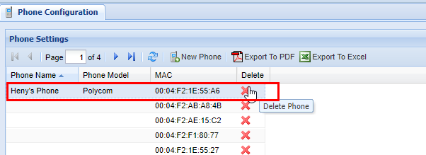
Removing a Phone
Caution should always be taken when removing a [Physical Phone Device]. Even if a phone may not be actively used by someone for placing calls, it may have a [Call Forward] in place. Ensure that all functions related to this phone are unused or unneeded before removing it.
2) Click on the phone you wish to delete and ensure that it's highlighted in blue
3) Next click the red X in the Delete column.
4) A confirmation pop-up will appear confirming your selection. If you wish to delete, click OK. You will see a message stating Changes Saved. If this is not the entry to wish to delete click Cancel.
Devices
Device Settings
| Name |
Description (What it does) |
Properties (How you interact with it) |
| MAC | The MAC address of a physical phone. | Every device must have a unique, properly formatted MAC address. |
| Main Extension | The device's assigned phone line. A device must have an extension to make or receive calls. | Extensions can be created on the Extensions screen. Two devices cannot have the same extension. |
| Main CallerID | Internal CallerID. This is seen only by phones on the same network. | Auto-filled based on assigned extension. Can be configured on the Extensions screen. |
| Main PhoneGroup Name | The PhoneGroup of the selected extension. Extensions in the same PhoneGroup will have some shared properties. | Auto-filled based on extension. PhoneGroup can created on the Phone Groups screen and assigned on the Extensions screen. |
| Phone Name | A name assigned to the phone. | An optional field used only for bookkeeping. |
| Phone Type | The manufacturer of the phone. | Must be POLYCOM or YEALINK. |
Additional Device Settings
| Name |
Description |
Properties |
| Phone Model | The model number of the phone. | An optional field used only for bookkeeping. |
| NTP Server | The address of the time server used to update this device's clock. | Optional. If blank, a default NTP server will be used. Typically only necessary for off-site phones. |
| Secure Provision | Determines whether this phone encrypts its provisioning information. Turning this on requires additional setup. | Off by default. Typically only necessary for phones using off-site or publicly accessible networks. |
DayNight Groups
Overview
DayNight Groups are often associated with collections of phones to set a pre-defined schedule for them. They can also be used to schedule many other things, such as Hunt Groups. Ultimately there are two modes, Day Mode and Night Mode.
Adding a New DayNight Group
2) Once you are within the DayNight Group screen click on the New DayNight Group button.
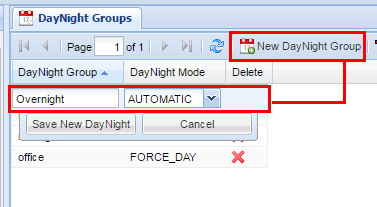
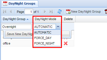
3) Fill out the DayNight Group name and the DayNight Mode option. The options for each DayNight Mode are explained below.
DayNight Group names cannot include spaces. If you wish to include a space in the name to so do with an underscore in between each name.
| DayNight Mode |
Function |
| AUTOMATIC | The setting follows the schedule as defined in the DayNight Schedule screen. |
| FORCE_DAY | This setting forces the DayNight Group to always be in Day Mode until it is modified otherwise. |
| FORCE_NIGHT | This setting forces the DayNight Group to always be in Night Mode until it is modified otherwise. |
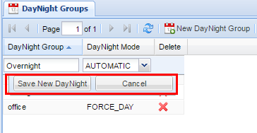
You won't be able to make any changes to the schedule through the DayNight Groups screen, To make changes to the schedule visit the DayNight Schedule Screen.
4) After you are satisfied with your selection, click the Save New DayNight button, afterwards, you should see a message at the top of the screen in green stating Changes Saved.
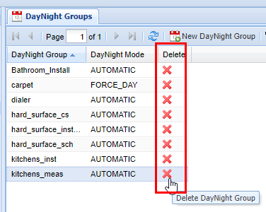
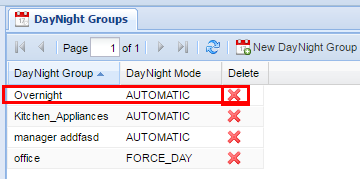
Removing a DayNight Group
2) Find the DayNight Group you wish to delete and click on the red X in the Delete column,
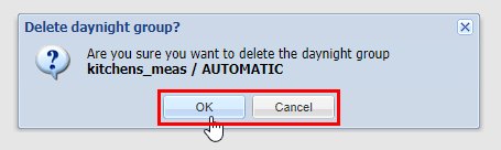
3) A confirmation pop-up will appear to confirm your selection. If you wish to delete, click OK. You will see a message stating Changes Saved. If this is not the entry to wish to delete, click Cancel.
When you remove a DayNight Group, you are also deleting the DayNight Schedule along with it. Ensure that this does not affect your organization's call flow in a way that was unintentional. If you have doubts regarding this action contact your system administrator before proceeding with deleting the DayNight Group.
DayNight Schedule
Overview
The DayNight Schedule screen is where you set the schedule for the DayNight Groups. You can set a permanent schedule as well as override periods where the schedule may need to be modified based on the current needs of your organization.
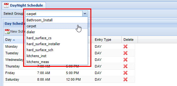
Group Selection
Before modifying any DayNight Schedule, you must select a DayNight group from the top left of the screen.
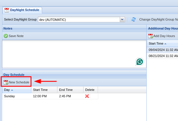
Adding a Day Schedule
2) Choose a DayNight Group to modify (see Group Selection)
3) To add a Day Schedule start by clicking New Schedule within the Day Schedule tab. You can also click on a pre-existing day if you are modifying the permanent Day Schedule.
4) A row editor will appear in the grid with several options.
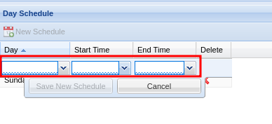
5) Select the appropriate day (each day must be set individually), start time, and end time.
6) After you are finished editing, click Save New Schedule. If the changes have been saved successfully you will see a green message saying Changes Saved. Repeat the previous steps to add additional days.
Removing a Day Schedule
2) Find the correct date to remove, and click on the red X under the Delete column.
3) A confirmation pop-up will appear. If you wish to delete, click OK. You will see a message stating Changes Saved. If this is not the entry to wish to delete click Cancel.
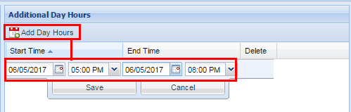
Adding Additional Day Hours
2) Find the Additional Day Hours panel located in the middle of the screen.
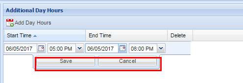
3) Click "Add Day Hours" and fill out the start date and time, and the end date and time.
If you need to have multiple days of additional hours at specific times (versus all day) you will need to make multiple entries, one for each day.
4) Click "Save" to add the entry.
Adding Additional Night Hours
Adding Additional Night Hours is performed the same way as adding Additional Day Hours except that you use the Additional Night Hours panel.
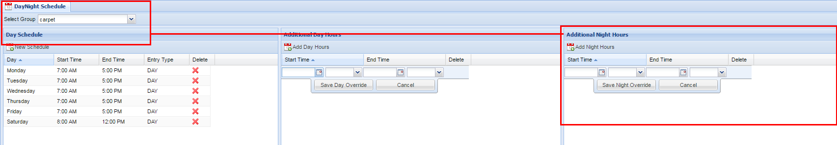
2) Find the Additional Night Hours panel located on the right of the screen.
3) Click "Add Night Hours" and fill out the start date and time, and the end date and time.
If you need to have multiple days of additional hours at specific times (versus all day) you will need to make multiple entries, one for each day.
4) Click "Save" to add the entry.
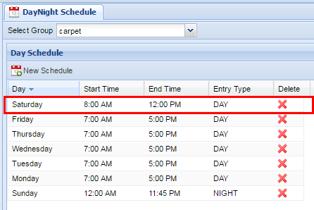
Example
Let's say we have a permanent day schedule of Monday through Friday 7:00 AM to 5:00 PM. An event is coming up requiring the selected DayNight Group to stay extra on Wednesday and Thursday for 2 hours, from 5:00 PM to 7:00PM. To accomplish this you will have to make two entries, one for each date. The reason for this is if you set a start time for additional hours of Wednesday at 5:00 PM through Thursday at 7:00 PM the entire range of defined hours will indicate that the DayNight Group is in Day Mode. If the phones are configured to receive calls in Day Mode they can potentially receive calls during hours that were not intended to be received (e.g. between 7:00 PM through 7:00 AM the next morning)
After you have ensured that have selected the correct range of hours, click Save. If the changes are successful a message will appear at the top stating Changes Saved.
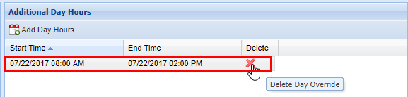
Removing Additional Day or Night Hours
2) Find the Additional Day Hours entry or Additional Night Hours entry that you wish to remove.


3) From the Additional Day Hours or Additional Night Hours panel click the red X in the Delete column.
4) A confirmation pop-up will appear confirming your selection. If you wish to delete, click OK. You will see a message stating Changes Saved. If this is not the entry to wish to delete, click Cancel.
Hunt Groups
Overview
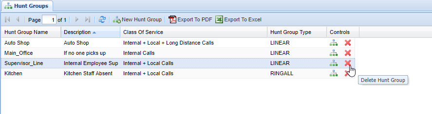
Hunt Groups contain Hunt Group Members, which are a collection of phones to be dialed until a party is reached. They can be set up to ring a collection of phones all at once, or one at a time in a set order.
Adding a Hunt Group
2) Next click the New Hunt Group button.
3) Enter a name for the Hunt Group. The name cannot contain spaces, if you wish to use a space use an underscore instead.
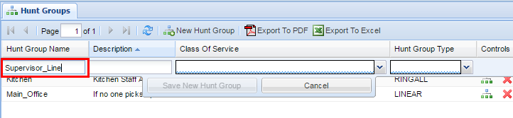
4) Enter a Description for the Hunt Group. The description should be brief but can contain spaces.
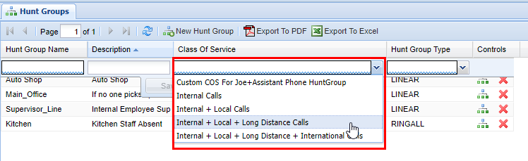
5) Choose a Class of Service for the Hunt Group. (What is a Class of Service?)
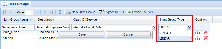
6) Select a Hunt Group Type for the Hunt Group. (See below for an explanation of group types)
7) After you are finished, click the Save button in the middle.
8) Lastly, you will need to add numbers (members) to the hunt group. Visit the Hunt Group Members page for more information.
Tip: To quickly edit the members of a hunt group, click on the green button on the far right under controls.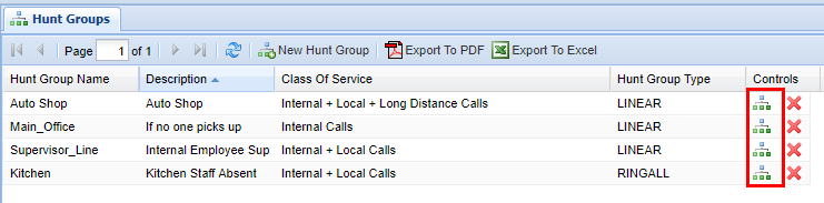
Hunt Group Types
| Hunt Group Type |
Definition |
| RINGALL | ALL members of the Hunt Group will ring simultaneously until the call is picked up. If the call is not picked up it will go to the unavailable destination that is programmed to that Hunt Group on the back end of the web portal |
| LINEAR | The members of the associated Hunt Group will ring in the chronological sequence defined in the Hunt Group Members screen. If a call is never picked up, the call will go to the unavailable destination which is programmed on the back end of the web portal. |
Removing a Hunt Group
2) Find the desired Hunt Group you wish to delete
3) Click the red X in the Controls column.
When you remove a Hunt Group, you are also deleting the Hunt Group Members associated with it. Make sure that this will not interrupt your organization's call flow. If you have any doubts about this contact your system administrator.
4) A confirmation pop-up will appear confirming your selection. If you wish to delete, click OK. You will see a message stating Changes Saved. If this is not the entry to wish to delete, click Cancel.
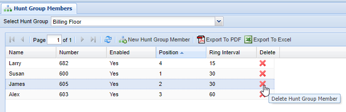
Hunt Group Members
Overview
A Hunt Group is a way to ring a group of phones, either in sequence or in parallel.
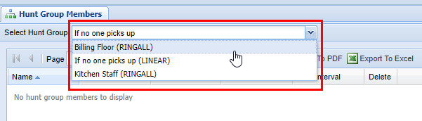
Hunt Group Selection
Before adding Hunt Group Members, you must first choose the hunt group to modify from the dropdown in the top left of the screen.
Tip: If the Hunt Groups were updated and are not visible in the list, reload the list by picking any group and pressing refresh or by navigating to a different screen and back again.
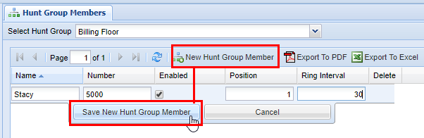
Adding a New Hunt Group
1) After choosing a Hunt Group, click the New Hunt Group Member button and fill out the row.
Tip: Unlimited members are supported.
|
Property |
Description |
|
Name (Required) |
The descriptive name of the number to ring. |
|
Number (Required) |
The number to ring, which can be any valid extension or 10 digit number. |
| Enabled | Whether or not the number will be active within the Hunt Group. |
| Position |
Only valid for LINEAR type. Each number will ring for Ring Interval seconds. If not picked up, the call will proceed with ringing the next number from smallest to largest in the position sequence until there are no more numbers to call. At that point, the call will be sent to the Unavailable Destination |
|
Ring Interval (Required) |
For a LINEAR type, the number of seconds the call will ring. For a RINGALL type, all enabled numbers will ring simultaneously for the set number of seconds. If not picked up, the call will be sent to the Unavailable Destination |
|
Ring Interval Retry |
If (And only if) this is non-zero, 'Ring Interval' becomes the sub-interval, and we'll ring up till 'Ring Retry Interval' seconds total.. |
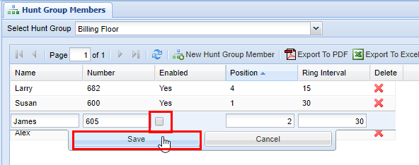
Enabling/Disabling Hunt Group Members
To disable/enable a hunt group member, double-click on the member's row and disable/enable the checkbox under "Enabled".
Disabling a Hunt Group Member is useful when one or more members may become unavailable or just not necessary to ring them for a certain period. When the member becomes available again, edit the record to set it back to Enabled.
Removing Hunt Group Members
1) Click on the red X, next to the member's name
2) In the dialog, click OK to delete.

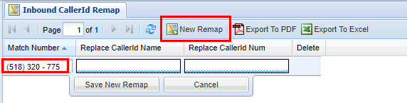
Inbound CallerID Remap
Overview
Inbound CallerID Remap allows you to set the Caller ID of external calls on a number-by-number basis. This is useful for phone numbers that don't have caller ID associated with them, that may frequently call into your organization.
It is not possible to use this feature to differentiate between people who call from hidden, private, or unavailable numbers. (However, if you wish to block calls from such numbers it is possible to do so. Contact your System Administrator for assistance.)
Adding a New Remap
3) Enter the Match Number you wish to remap. This is the inbound number that will be remapped to a new name and/or phone number.
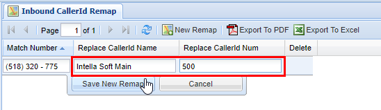
4) Next enter the Replace CallerId Name associated with the Match Number. This is the name that will show up in your organization's Caller ID when it matches an inbound number that is calling.
5) Additionally, you may also replace the inbound number to show something different in the Replace CallerId Num.
You can use a custom name (Replace CallerID Name), custom number (Replace CallerID Num), or both.
6) After you are satisfied with what you have entered, click Save to save the New Remap. After you Save you will see a message stating Changes Saved.
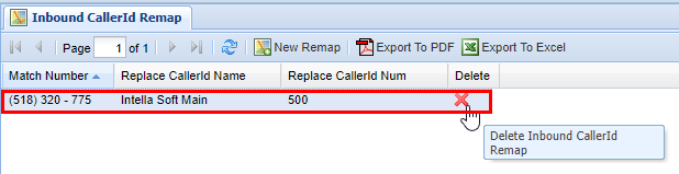
Removing a Remap
2) Select the Remap you wish to delete
3) Then click on the Red X in the Delete column.
4) A confirmation pop-up will appear confirming your selection. If you wish to delete, click OK. You will see a message stating Changes Saved. If this is not the entry to wish to delete, click Cancel.
Phone SysDial Directory
Overview
The Phone SysDial Directory is a mapping of "Short Codes" to full phone numbers. Shortcodes are useful for quickly dialing commonly used external phone numbers.
A shortcode is a shorter number that can be dialed to reach a full number. Think of them as abbreviations for phone numbers.
Adding a Phone SysDial "Short Code"
2) Click the New Sysdial Number button.
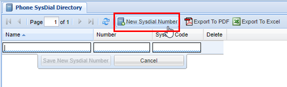
2) Enter the Name of the short code. This should be relevant to whom the number is associated with.
3) Next enter the Number that the shortcode should dial. This can be an internal Extension, or it can be an outside phone number.
4) Lastly enter a number for the shortcode in the box Sysdial Code. This is the number the user will dial when attempting to call the full Number associated with the shortcode.
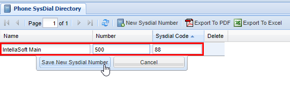
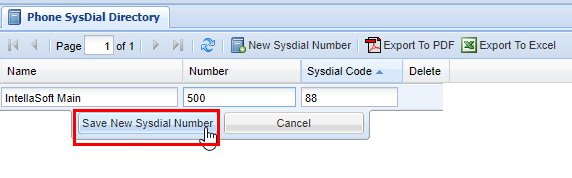
5) When you are satisfied with your selection, click Save New SysDial Code. If you saved you will see a message stating Changes saved. The final results will look similar to the one below.
If you enter a 10-digit external phone number, it will automatically format the phone number to include the area code in parentheses followed by the local number.
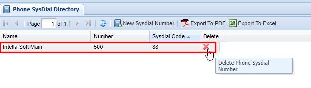
Removing a "Short Code"
2) Find the SysDial Number (short code) you wish to delete
3) Click the red X under the Delete column.
4) A confirmation pop-up will appear confirming your selection. If you wish to delete click OK. You will see a message stating Changes Saved. If this is not the entry to wish to delete click Cancel.
PhoneMap Groups
Overview
A PhoneMap Group is a one to one mapping from one destination to another. There can be multiple PhoneMap Group Members, but only one should be active at all times.
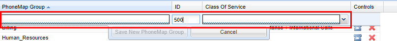
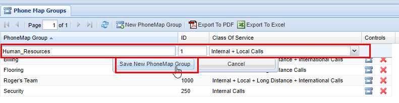
Adding a New PhoneMap Group
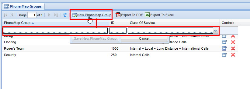

Enter a PhoneMap Group Name, and PhoneMap Group ID, these are up to preference but should be based on your organization's need. The ID must be a [Token]. Lastly select an appropriate Class of Service for the PhoneMap Group. When you are finished click Save New PhoneMap Group to save the PhoneMap Group, otherwise click Cancel. After you have saved you will see a message stating Changes Saved.

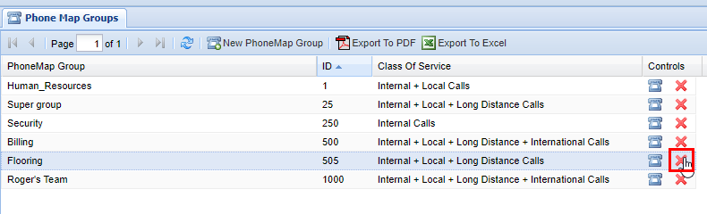
Deleting a PhoneMap Group
It is important to remember that when you delete a PhoneMap Group that any of the mappings that fall under the PhoneMap Groups will also be removed. Always double check the mappings to ensure that no phones that are critical to active phone system will be removed. If in doubt, contact your system administrator. For more information on PhoneMap Group Mappings and Members click here.

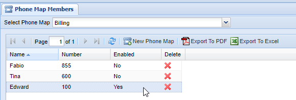
Phone Map Members
Overview
The Phone Map Members screen is similar to the Hunt Group Members screen in which all it is is a screen dedicated to adding the actual Phone Map Members to.
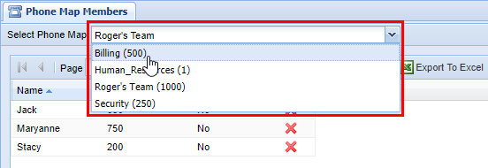
Group Selection
When you are modifying Phone Map Members you do so by selecting an appropriate Phone Map Group. Before editing a Phone Map Group and it's Phone Map Members ensure you have a proper group selected by selecting one from the drop down menu labeled Select Phone Map Group, which is at the top left hand corner of the Phone Map Members screen. The Phone Map Group in the drop-down is referenced by it's Phone Map Group Name as well as ID, which was setup in the Phone Map Group screen.

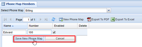
Adding New Phone Maps
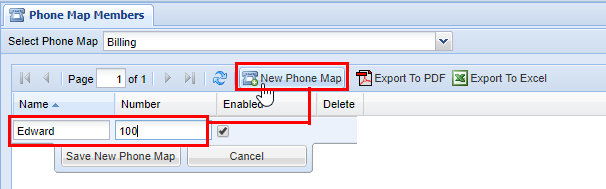

When you are satisfied click Save New Phone Map otherwise click cancel. You will see a message stating Changes Saved if the number has saved successfully.

Repeat the previous steps until you are satisfied. You are able to have an unlimited amount of phone maps added to a Phone Map Group however the phone maps are designed for a 1 to 1 configuration, meaning only one number can be active at a time. If you wish to use multiple numbers in a phone map group, you should use a Hunt Group instead.
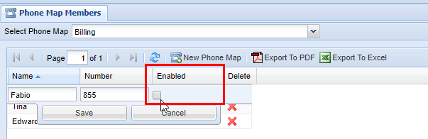

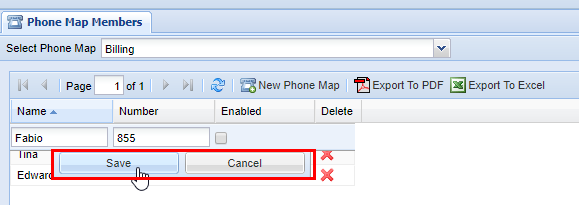
To enable/disable a number, click on the row you wish to modify. Afterwards, check the box to enable or disable the phone map group member. When you're finished click Save, you should see a message stating Changes Saved after.

Repeat the previous steps as necessary to ensure that only one phone map member is enabled, while the others are disabled. This is indicate by a Yes (for enable) or No (not enabled) in the Enabled column.

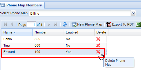
Removing a Phone Map Group Member
A confirmation pop up will appear confirming your selection. If you wish to delete click OK, you will see a message stating Changes Saved, if this is not the entry to wish to delete click Cancel, to return to the screen. Afterwards, ensure that an appropriate Member in the PhoneMap Group is enabled, this will be up to your organizations needs. If you do not enable a member after deleting a member that has been previously enabled (such as the example here), then this Phone Map Group will not have an active member available to receive calls. If however, you simply deleted a member that is disabled while another remains enabled, no further action is necessary.
Voicemail
Overview
The Voicemail screen is for looking at organization-wide voicemail boxes as well as your own. The voicemail boxes you have access to will be dependent on your User permission settings as defined in the Users screen.
General Voicemail Overview
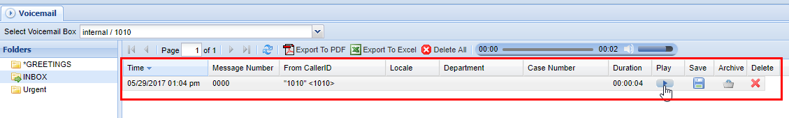
Select the Voicemail Box you wish from the drop-down menu labeled Selected Voicemail Box. This can be found at the very top of the screen under the Voicemail tab. From here a list of all the Voicemails you have access to will appear. The Voicemail Boxes will depend on your User Permissions.
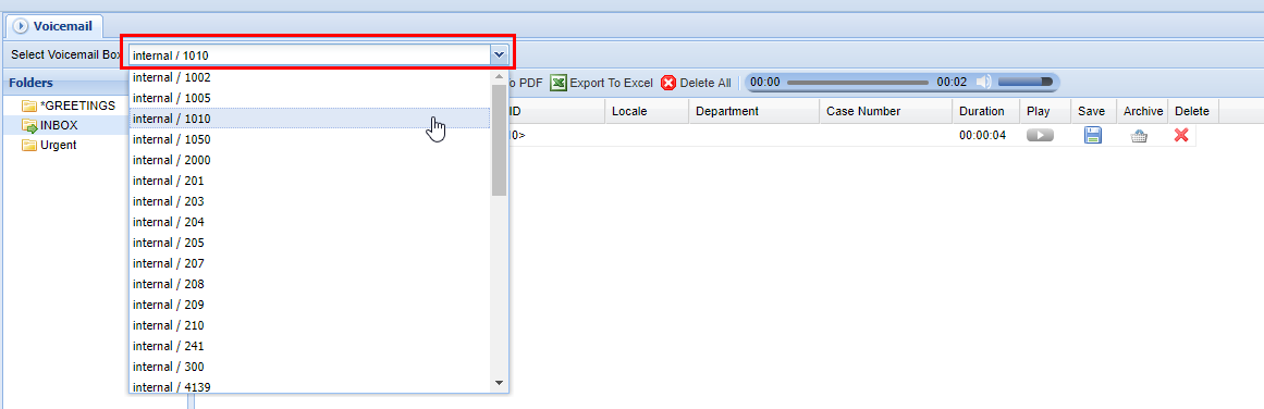

Next, on the left side of the screen, depending on the User's voicemail box setup they will have multiple folders available. These will depend on the user's/organization's needs or preferences. For this example, we select the voicemail box of INBOX.
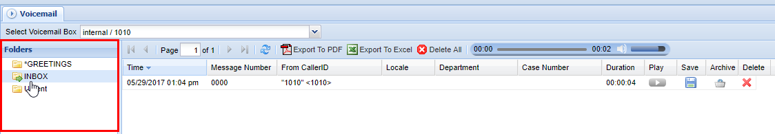
Afterwards a list of all the available voicemails to be listened to will populate. Several columns will display information about the specifics of the voicemail. See the table below as a reference to each of the column's functions.
| Column |
Description |
| Time | The time the message was received. |
| Message Number | Message number in accordance with it's order received in the Voicemail Box |
| From CallerID | Name or Number from which the caller originated |
| Locale | Location (usually will be a City, State) where the call originated. |
| Department | Customer-specific, you may not have this view. |
| Case Number |
Customer-specific, you may not have this view |
| Duration |
Length of the recorded voicemail |
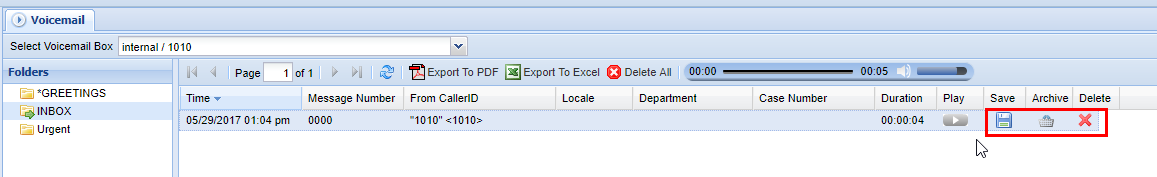
On the far right, you will see a list of actions you can take on the voicemail.
| Action |
Description |
| Play | Play the recording for the row selected. |
| Save | Saves the recording to local storage as a .WAV |
| Archive | Places the call in a separate folder for later viewing. |
| Delete | Permanently deletes the call from the voicemail box. |
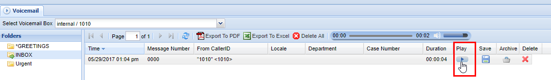
To play the voicemail click the Play button.
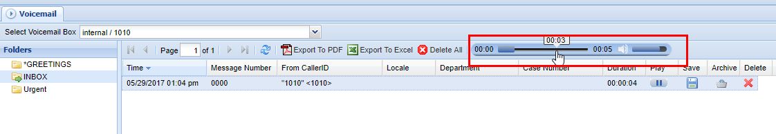
When you play a voicemail, its duration will appear in a status bar in the toolbar, it is possible to click throughout the status bar to skip to different portions of the voicemail, as well as alter the volume as needed.
When you are finished, you can leave the voicemail alone, or you have the option to Save, Archive, or Delete the voicemail. See the table above.
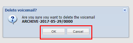
When deleting a voicemail you will always be prompted with a pop-up confirming your selection, as always if you wish to delete the item click OK, otherwise click cancel. In this particular circumstance, this is an archived voicemail that has been moved to a separate folder, it renames the voicemail with the date and voicemail number.
Call Logs
Overview
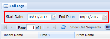
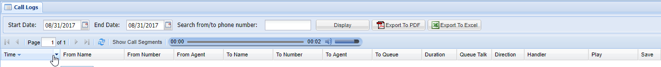
The Call Logs screen contains powerful features for accurate call logging. Say you have an exact date or range of dates that you wish to check calls from, you can do this with the call date filter function. At the top right hand of the screen, you will see Start Date and End Date with dates to the right of them, with a calendar icon in the box. You can manually enter a date for both of these with a Day/Month/Year format.
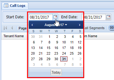
Alternatively, if you click on the calendar icons themselves, a pop calendar will appear allowing you to graphically choose a date to filter for.
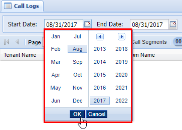
To quickly select a specific year and date, you can click on the Month/Year above the dated calendar. From here you can choose a specific year to center the calendar too. After you do this simply click OK, and it'll bring you back to the dates, in which you can click on the date in question. After you click a specific date, the calendar will disappear showing that the date has been inserted into the respective box for Start Date or End Date. Whenever you select a set of dates to filter by the screen will refresh automatically displaying any matching calls in the grid below.
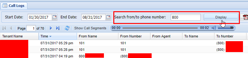
You also can filter by incoming or outgoing numbers. To the right of the Start Date and End Date function, you will see the option to Search from/to phone number: with a box to the right. In the box, you can enter a complete 9-digit number or even a partial number to filter the call log. Enter a number that you wish to filter by, and then click the button labeled Display to the right.
The Call Logs grid shows a lot of information about the calls it tracks. By now you should be familiar with how to navigate multiple pages in the web portal as well as the core functionality of the web portal as well, if you aren't then reading the Web Portal Introduction will help with understanding some of the specific functions/buttons not covered here. Please note that this is an abbreviated overview of the Call Logs screen from a live system and as such sensitive information has been censored.
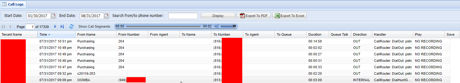

Below is a table, explaining the various columns in the Call Logs screen going left to right.
| Column |
Description |
| Time | Time call was received/placed |
| From Name | Who the call was from |
| From Number | Phone Number the Call Originated from (extension, full number, etc.) |
| From Agent | If the call was from an agent which agent it was from |
| To Name | Who the call was to |
| To Number | The number the call was placed to |
| To Agent | If call was placed to an agent, the agent the call was placed to |
| To Queue | Queue the call was placed to (if applicable) |
| Duration | Duration of the entire the caller was connected (including in queue, live person talk time, etc.) |
| Queue Talk | Total time talking to a live person |
| Direction | The direction of the call will be noted here. Either IN, OUT, or INTERNAL |
| Handler | This is the application that handed processing the call, Example: CallRouter for direct dialing, or CallQueue if this was a inbound CallCenter call |
| Play | Plays a recording if one is available, if it not available there will be a status as to why |
| Save | Save the recording as a .WAV file (if available) |
As you can see by the table above you can play and save call recordings if they are available. It is important to keep in mind that the grid will show all applicable calls as shown in accordance with what filters have been set. These filters include the date filters and number filters as shown above, but additional filters can be applied per the columns filtering utility, for more information on grid filtering, check out this section of the Introduction. Please note that this is an abbreviated overview of the Call Logs screen from a live system and as such sensitive information has been censored.

Support and Troubleshooting
Asking the right question
First, let's ask the 'wrong question'
Here are some quick tips on how to get the right answer you need, by asking the 'right question'.
Imagine this situation:
- You are a novice car mechanic.
- You have noticed a problem with your car shifting into drive
- You have some skills to trace and troubleshoot the issue and have reasonable suspicion that the problem is with the transmission.
- You do some research and find it might be pressure-related
You then ask the master mechanic at your shop:
- How do I double-check I have the right pressure for my transmission fluid?
The local master mechanic then proceeds to spend 30 minutes training you on this topic. Then you check the pressure it is correct. Now what?
Next, let's ask the 'right question'
There is never an exact way to find precisely the 'right question', but we can start by 'backing out of the weeds'. Or zooming out on the problem.
Don't focus on a specific detail of the problem. Instead, focus on a high-level view with as much detail as possible
What is our ultimate goal? We want to fix shifting
What do we know so far? Not much... shifting doesn't work.
But wait... we DO know more information... if we change our perspective and how we think about this problem
You now tell the master mechanic
- I have a problem shifting in this vehicle
- The issue happens when I'm going from neutral to drive
- The shifter lever does not move
The master mechanic thinks about this for 30 seconds and responds with
- Check the connecting rod from the shifter to the transmission
- You check the rod and it's broken.
- You replace the rod and shifting works perfectly now
In this scenario, while you thought the issue was transmission-fluid related from doing the research ... the answer clearly lies in a different direction entirely. The focus was too much on a 'specific thing' rather than the overall picture.
Moral of the story
When we asked the 'right question' we got the answer almost immediately. Of course not every situation is as cut and dry and as straightforward as this is... but if you ask your mentor, project lead, or other resource the 'wrong question' you're going to still be miles away from solving your problem because it's too detailed... to deep in the rabbit hole to be useful for solving your problem.
While never a bad idea to get extra training... extra training can always be done (and should be done) during 'downtime' when customers aren't waiting for jobs to be completed. The ultimate goal is to fix the problem for the customer. Detailed learning and understanding are great, but it's important to focus on those aspects after the problem is solved when you have a relaxing time to absorb and learn.
Examples
Wrong question: How do I make the swap file smaller?
Right Question: I need to clean up disk space, what large files should I delete first?
Analysis: While you might think shrinking the huge swap file is a great way to save disk space... perhaps the real problem is the 500 gigabytes of files in 'Downloads'
Wrong question: How do I make this phone register more often?
Right Question: I'm having a problem with a phone registration dropping out... the user can't make calls after 5 minutes. How can we troubleshoot the network?
Analysis: Registering more often won't fix the problem if it's a broken or misconfigured network. This is why backing out to the 'high level' question is better
Wrong question: How do I turn off the blinking light on the phone?
Right Question: I have a phone, where every time the user gets a voicemail, the light goes on... they would rather get an email for new voicemail messages.
Analysis: The 'Blinking light' could be related to many possible reasons. Lights blink during startup, during configuration reload, for warnings, or for voicemail.
Collecting Call Examples
Overview - Help Us, Help You
When encountering a call behavior issue, routing issue, dialing issue, and just about any other communications-related issue, it's very important to note some key points of information. This will help the technical support team to diagnose the problem.
What to do if a call has failed to connect, or other call-related issues occur.
The following points of information represent what is referred to as a "Call Example". Call Examples are a key component in troubleshooting just about *any* type of issue, disruption, or problem that might occur on your communications system.
Please collect these three Critical Details about your call so that the technical support team can look into your issue
1) Date and Time of occurrence
- If you can, please try and notate the time to the closest minute that the issue occurred
2) What phone number or extension was being called
- If you are calling an internal extension, please note the extension being called
- If you calling an outside number, please note the full phone number
- If you are calling another branch or office location, please note the name of the location you intend to reach as well as the number dialed
3) The extension or number that the call was placed from
- If this call was placed from inside the office or otherwise is part of the office system, note the extension used
- If this call was placed from outside the office, please provide the full phone number (CallerID) of the received call
Also, please try to be as detailed as possible and provide the following Additional Information if possible.
- Action: What is the task or action that was attempted? Example: "We tried to access voicemail at the Main Street Office from the Maple Street Office"
- Expected: What was the expected behavior? Example: "We expected to be able to access the voicemail box of extension 155"
- Result: What was the actual behavior? Example: "We experienced an odd tone, it was three beeps and then the call hung up, then the announcement told us that Error 55 has occurred"
Here are some example reports
Example One - The Great Example
| Reporter Notes |
Analysis |
| Issue occurred at 12:25pm Eastern Time on June 5th when calling *123 from extension 1000 | This is a perfect start of a Call Example report. It concisely describes all three critical details of a Call Example. |
| Tried calling into voicemail in order to change a greeting. Twice we got a busy signal, and two more times we got a weird buzzing. The fifth time we got in and changed the greeting. |
This is a great level of detail without a lot of writing! The reporter concisely described what they were trying to do (the Action), what they Expected (access to voicemail for the greeting change). The reporter stated how many times they tried to do the action (this can be incredibly helpful to the support staff). The reporter also stated what occurred when each attempt was taken (the Result). It's important to describe how the call failed. The technicians working on your issue will be keyed into the problem area by error codes and sounds. Buzzing may very well indicate a wire has been physically damaged. Beep codes from the system or your service provider will give clues to the source of the problem. |
Example Two - The "OK" Example
This type of report may result in delays in resolving the issue while the support team shuffles through troubleshooting data to locate specifics.
Suppose a reporter was having the same problem as described in Example One, but reported the problem in this way:
| Reporter Notes |
Analysis |
| Issue occurred at around 12:00pm in June 5th when calling *123 from extension 1000 |
This is an "OK" start of a Call Example report. The time is vague, but with the date, the technical support staff can locate the problematic call with some searching and poking around to find the specific calls that started at 12:25. Also, the time zone has not been specified in this example. Depending on where the reporter is located and where the staff is located, there may be some guessing involved in locating the correct Time Zone to apply when searching the system data. |
| Voicemail had a problem, we were disconnected a few times, but we did get through once. |
This note provides some detail. The reporter has noted the Action (voicemail), and the Result, but didn't relay the Expected -- Why is the Expected item important you might ask? If the support team understands what you are trying to accomplish, they can suggest Alternative ways to complete the goal while they work on the issue. The support team immediate response to Example One would be to use the web portal to change the greeting in the meantime, while we troubleshoot the issue dialing into voicemail. Also, the reporter in this example did not give any detail on which attempts were failures and which attempts were successful. When the support team is working on the reported issue from Example One, they may be able to locate the issue within minutes, given the specifics, since the team knows exactly what to look for. When the support team is working on the issue reported from Example Two, it could take an hour or more to sift through data, and system reports to locate the problem. |
Example Three - The Poor Example
This type of report will most certainly result in a serious delay in resolving the issue that has been reported. The support team may take hours or days to locate the calls in question
| Reporter Notes |
Analysis |
| One of the phones called voicemail, the problem was during the first week of June. |
This is a poor start of a Call Example report. There is a vague starting point of investigation (first week of June). There is no time listed, and no extension listed. The support team might not be able to locate the problematic call if this phone is part of a large system. Depending on the size of your installed system, sifting through hundreds, thousands, or tens of thousands of calls over a period of a week is not going to be an effective way to solve this problem. Also, the reporter has not defined what the problem is. The support staff will not know what to look for! It is possible that the support team may be unable to investigate or resolve this issue. |
| (No Additional Information supplied) |
This reported example provides very little detail. The reporter has noted the Action (voicemail) and a very vague Result (a problem). Depending on the size of your installed system -- Every minute, hundreds or thousands of data points are recorded on the communications system. Given this level of detail that is recorded, there may be no realistic way to locate the problem. Without ample information, the support team may decline to work on this issue until more information is available. |
Cook Book - Recipes
Creating a Call Forward using a DayNight Schedule

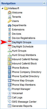
Overview
Welcome to the web portal documentation.
- The best place to start is the Web Portal Introduction.
- This covers how to get started, including:
Important topics for administrators are:
For more advanced system customization see:
- DayNight Groups / DayNight Schedule
- (Example use: Set the day time hours and night time hours for your main phone number)
- Hunt Groups / Hunt Group Members
- (Example use: Ring a group of phones)
- Phone SysDial Directory
- (Example use: Organization-Wide short code dialing)
- PhoneMap Groups / Phone Map Members
- (Example use: Rotating on-call routing in your organization)
For details on troubleshooting and support, see:
- Collecting Call Examples
- (When something goes wrong, technical support will need some basic information about the issue)
Generate Reports
| Field |
Description |
| Max Simul Calls | |
| Avg Simul Calls | |
| Max Simul Calls In | |
| Avg Simul Calls In | |
| Max Simul Calls Out | |
| Avg Simul Calls Out | |
| Avg Call Duration | |
| Max Call Duration | |
| Tot Call Duration | |
| Num Calls |
ScreenPop User Onboarding
Setting the Extension
If the user is taking over an existing Extension, locate that Extension, double click on the row and then the row will turn into an editable form.
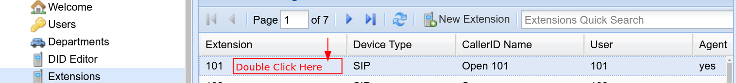
Once the editable form is shown, update the details for the Extension. If the Extension was automatically generated as part of the system setup, the User will have already been assigned, but if not make sure the User matches the Extension.

Scroll to the right on the main panel in order to see Voicemail related options.
The Voicemail Email is required for setting up the softphone for screenpops.
Click the Save button below the row once the editing is done.
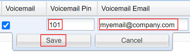
After the above is saved, the last extensions update is to go to the Additional Extensions Settings on the right hand side of the page.
Scroll down the settings to find the Phone Make and Phone Model.
Set the Phone Make to IntellaPhone and IntellaPhone PC should automatically get set. Then save.
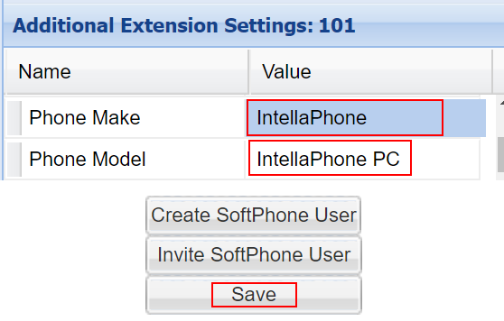
Once saved, click on the Invite Softphone User button. The user can then follow the directions to get their softphone setup → IntellaPhone
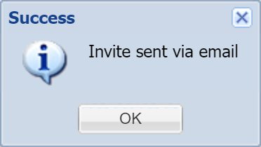
Jump to the below section: Setting The Agent.
Creating a New Softphone Extension If Necessary
If the user already has a deskphone and needs a softphone, start by selecting their existing Extension in the grid.
Then click the button Create SoftPhone User
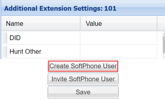
An automatic prefix of 2 is added to the softphone extension.
Everything should auto populate and then click Save
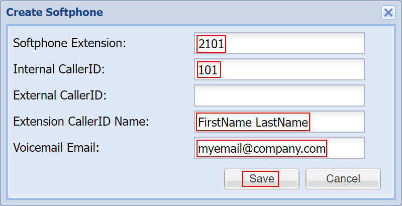
After the system creates the softphone, a success message appears.
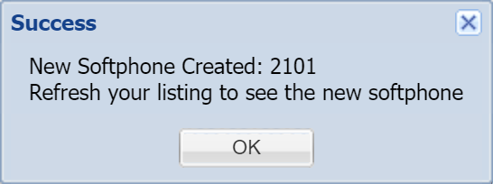
To refresh the grid, click the double arrow Refresh button, then the new softphone will appear in the extensions list
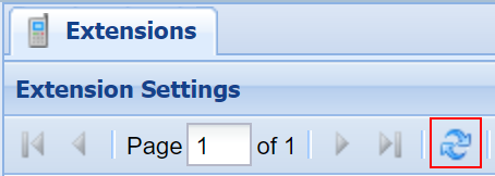
Then follow the same instructions as the top as if it's an existing extension.
Make sure the new softphone extension is selected, edit the row if necessary.
Double check the Additional Extension Settings, Phone Make & Model that they are set to IntellaPhone.
Once everything is updated and saved, proceed with the same Invite Softphone User.
The user can then follow the directions to get their softphone setup → IntellaPhone
Setting the Agent
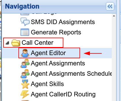
The Quick Search can be used to check if the Agent has already been added to the system.
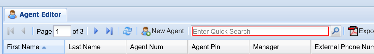
If not found, click New Agent button and a form will be shown. Populate all of the highlighted fields below and then save the new Agent. Keep in mind as a best practice to ensure that agents have a unique Agent Pin number for their logins.

Next, using the left navigation sidebar, navigate to Agent Allocations
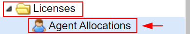
If you have no Agent Allocations, click the New Agent Allocation button and a form will be shown.
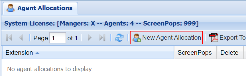
Populate the highlighted fields and then save the new Agent Allocation. ScreenPops checkbox is required for the agent to receive screen pops.
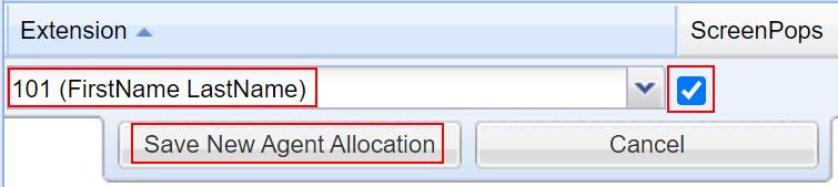
Now that the Agent is in the system, using the left navigation sidebar, navigate to Agent Assignments
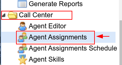
First, use the Select Queue list selector on the top.
The Quick Search on the right can be useful to locate the new Agent, and then use the green left arrow to add the chosen agent to the Queue.
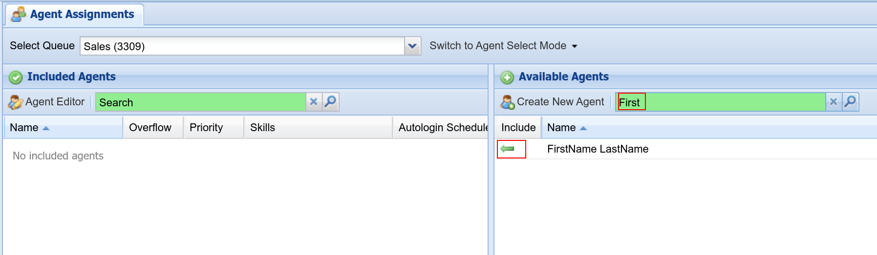
Lastly, test the new login by going to the Toolbar URL specifically for your system and then logging in with this Extension/Agent Number/Agent Pin
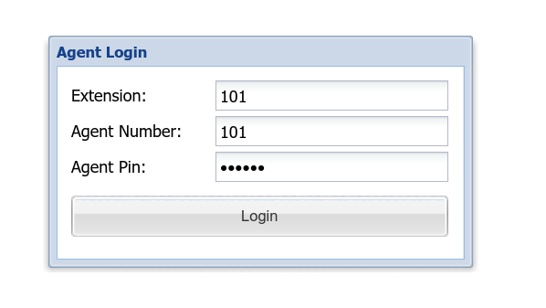
Setting a Manager
If there is a need for a User to be able to look at Call History and Call Recordings, then they will need to have a Portal Account (which is different than the Agent Login that's covered above).
Using the left side navigation sidebar, navigate to Users
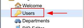
Then on the center panel, use the New User button to create a new User.
Use the Quick Search to determine if there already is a User for this person.
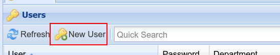
In order for a User to have access to all Calls, they will need the following set:
Department: admin
Permission Mode: Exclude
Permissions: Call Logs, Call Recordings, Call Recordings Other
Make sure that User and Password are both set in the row editor form, as well as Department, otherwise the User cannot yet be saved
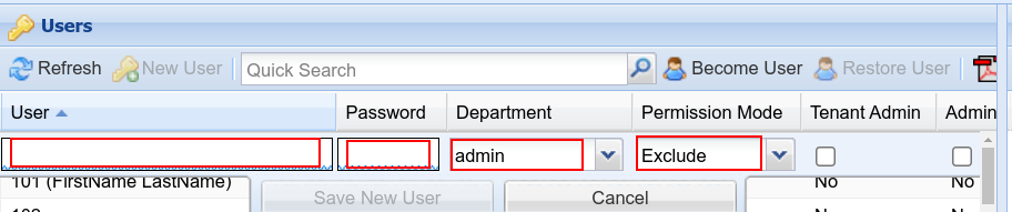
Scrolling over to the right will be required in order to set the necessary permissions.
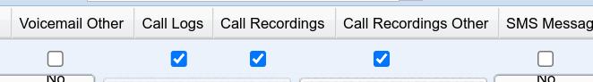
There are many possible combinations of access available, including access that restricts users to certain calls. The above is the simplest way to give a user access to all calls in the system.
What's New
2026 - June - Update 2
- 'Blank' is now available for Yealink Phone Button Provisioning
- This will fill a button slot with an empty space on the phone
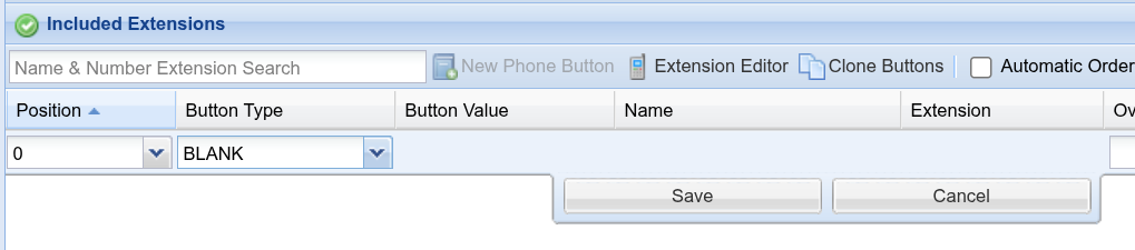
2026 - June - Update
- Quick Search is now available on all screens
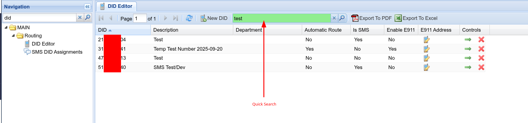
2026 - Mar - Update
- IVR: DayNight
-
It is no longer required to have 'Query DayNightSchedule' in order to get the DayNight status.
-
You can now just directly use 'If' and 'DayNight' together, without first doing 'Query'
-
This change is backwards-compatible. You can continue to save/edit older style DayNight sequences

-
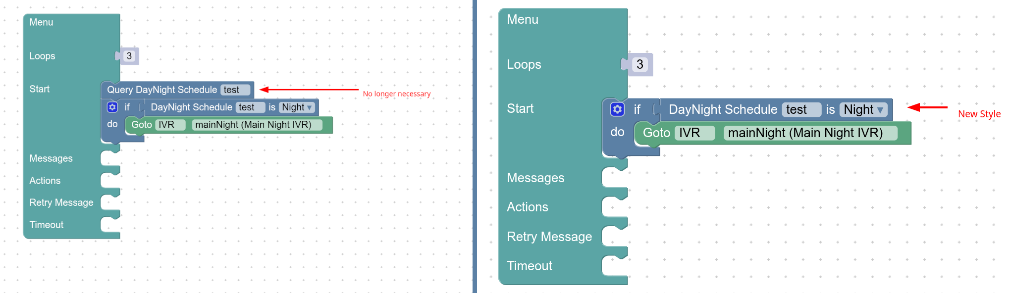
2026 - Feb - Update
- Phone Buttons - Loading speed efficiency update: up to 840% increase in speed!
2026 - Jan - Update 2
- New Feature: Edit E911 Address
- Now you can update associated E911 location addresses with your DID Phone Numbers

- Ensure that you dial 933 to test Emergency Services after updating addresses.
- Note: (Dialing 911 without an emergency may lead to State Imposed Fines)
See this guide on how E911 functions and how to fully do setup and testing: Here
- Note: (Dialing 911 without an emergency may lead to State Imposed Fines)
- Now you can update associated E911 location addresses with your DID Phone Numbers

2026 - January - Update 1
- New Feature: Call Center -> Agent Assignments -> AutoLogin Schedule.
- When using Call Center, this allows for automatically logging in an agent based on a DayNight Schedule

- When using Call Center, this allows for automatically logging in an agent based on a DayNight Schedule
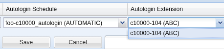
2025 - November - Update 1
- IVR Editor -- Expanded ComboBox for long prompt names
- General -- Errors now pop over all over panels
- General -- Errors with XML output now properly show
- Dialer Campaigns properly shows per-call-type settings based on what type being used (Call vs SMS)
- Dialer Campaigns -- Fixed margins and PropertySheet 'creep' w
- hen clicking
- SMS Message Screen now is refreshed after deleting a message
2025 - October - Update 2
- Multiple Yealink SideCars now supported
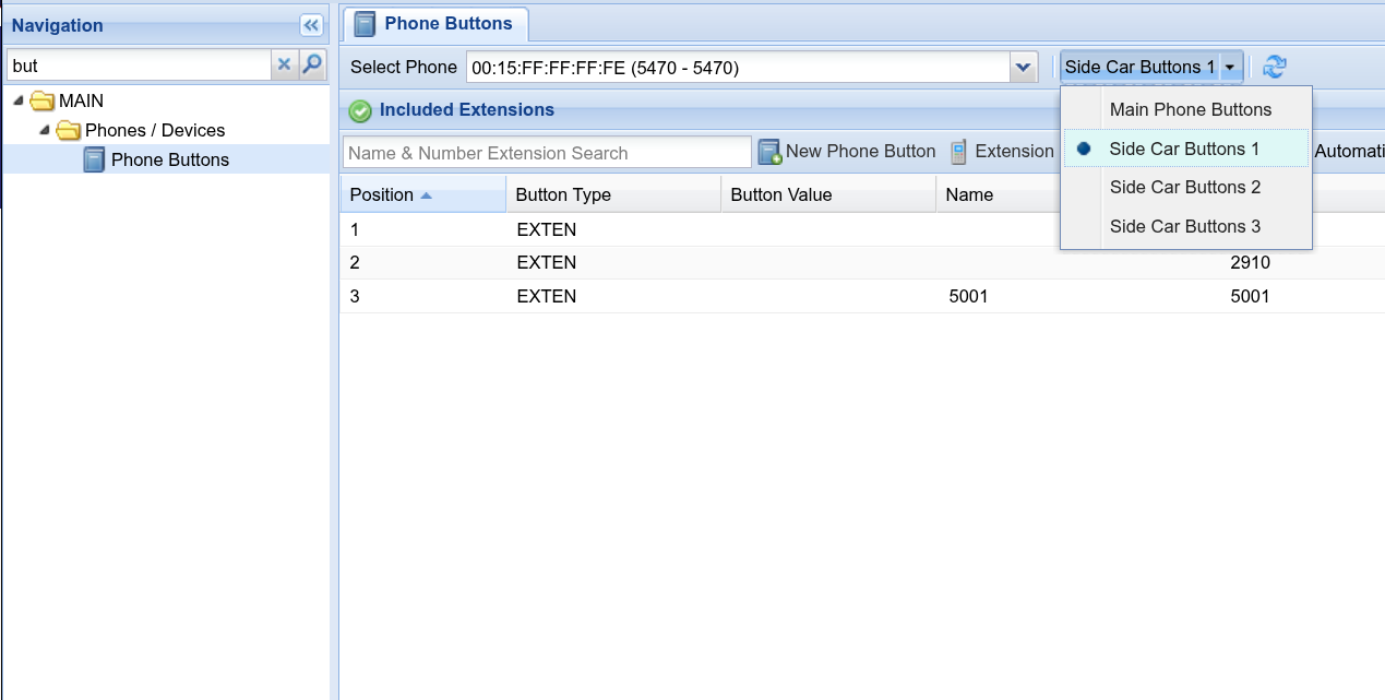
2025 - October - Update 1
- Navigation has been grouped
- Now, various configuration screens are grouped by category in order to more easily locate what's needed.
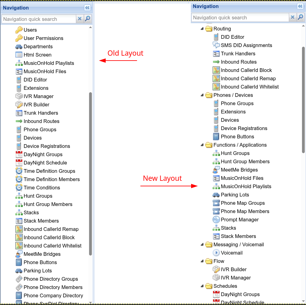
2025 - September - Update 6
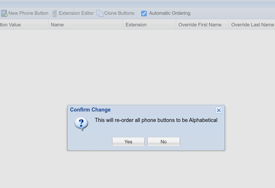
2025 - September - Update 5
- Navigation Redesign
- Navigation is now logically grouped by general category

- Navigation is now logically grouped by general category
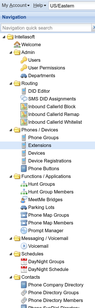
2025 - September - Update 4
- HuntGroups Redesign
- The HuntGroups grid has been simplified so it fits well on smaller screens
- HuntGroups now have an option for 'Missed Call Behavior'
- Options:
- Normal - This is the new default when creating new HuntGroups.
- This setting will only leave a missed call if the call has not been answered by the huntgroup
- Always - Always leave a missed call on all phones in the HuntGroup, even if the call is answered
- Never - Never leave a missed call on any phone in the HuntGroup, even if the call is missed
- Normal - This is the new default when creating new HuntGroups.
- Note: The previous default was 'Never'. All existing huntgroups that have been created before this update have been set to 'Never' to keep existing behavior.
- Options:
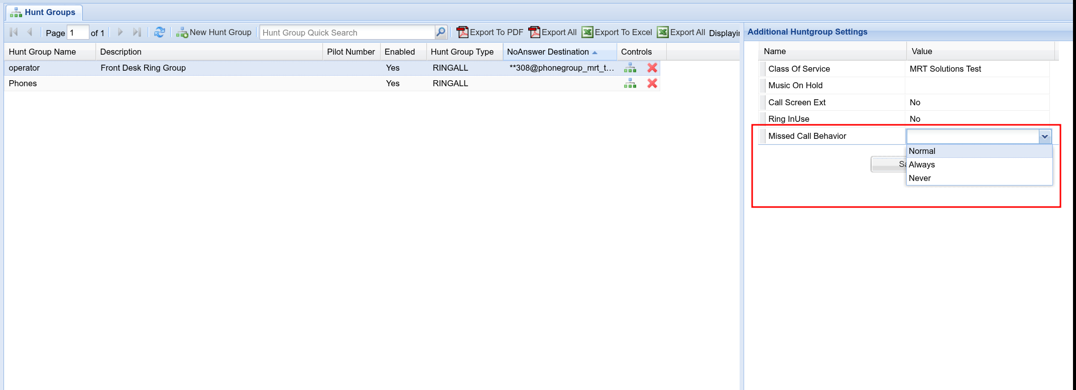
2025 - September 8 - Update 3
- Device Registrations 'There is now an All view for showing device registrations across all phones

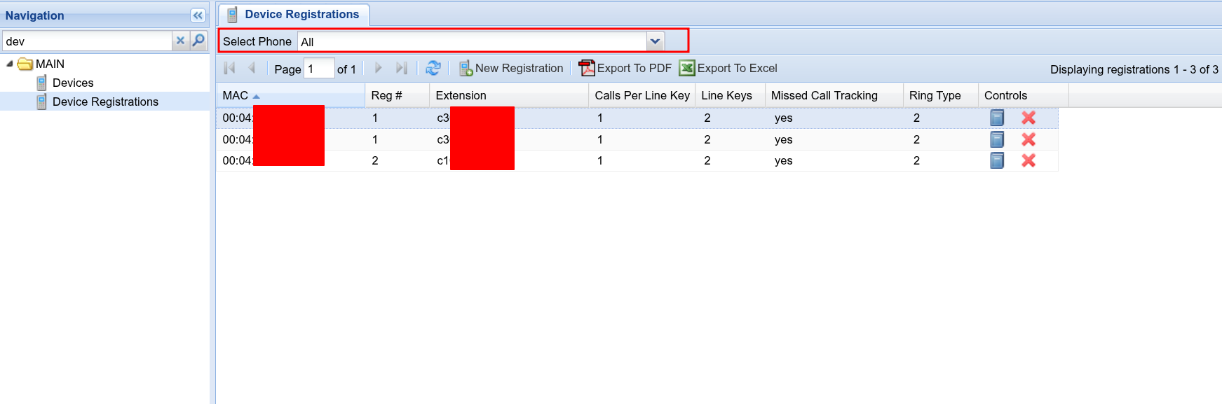
2025- September 8 - Update 2
- Extensions 'Additional Extension Settings' has changed to be easier to manage on smaller screens

2025 - September - Update 1
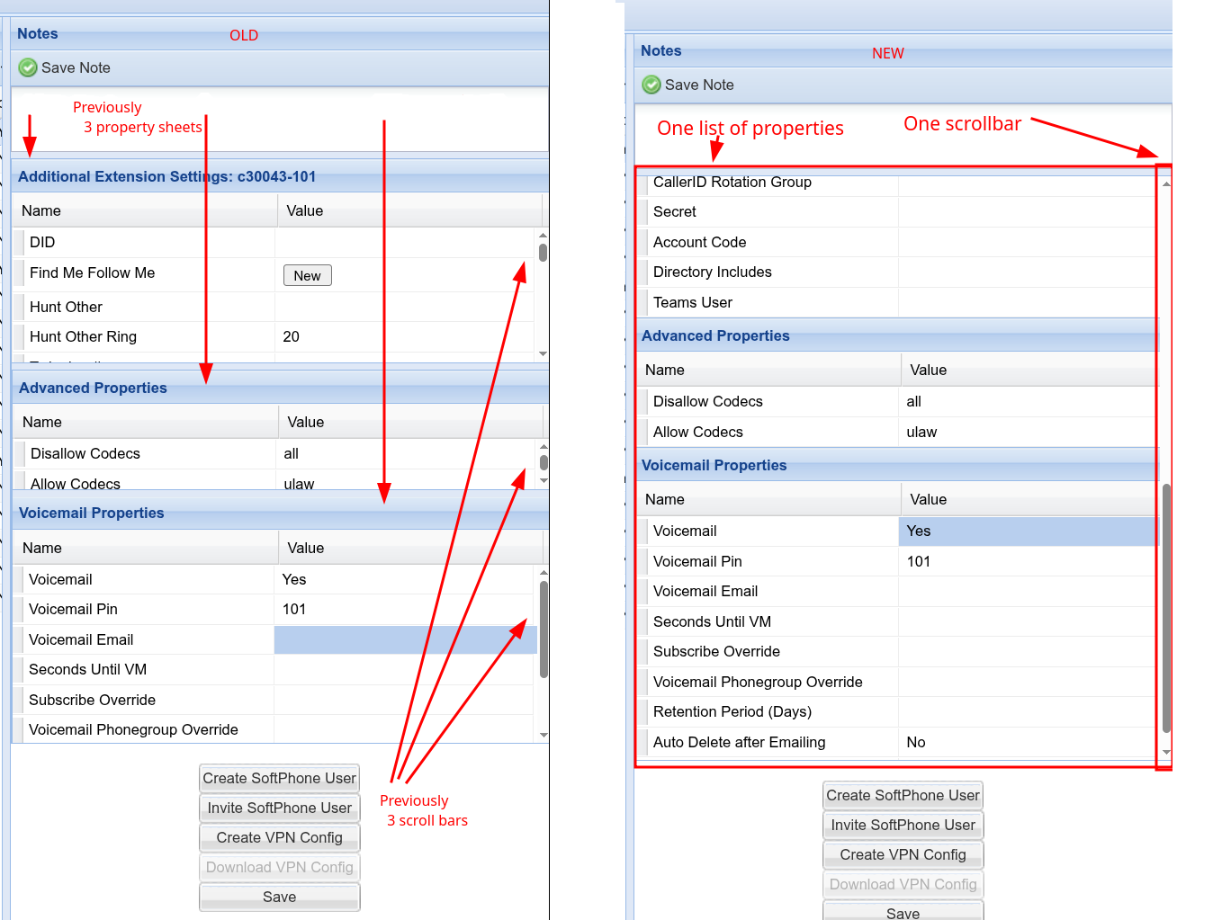
- IVR/Blockly: New Feature: If Time
- IVR/Blockly: New Feature: Set Test Time
- Example Usages
- - You can now do checks like: July 4... and the system does NOT care about a SPECIFIC calendar date. it will check for July 4 for any year
- - 8:00-9:00 -- This will check if it's ANY DAY between 8 and 9 am. Make sure to use 24h times.
- - 8:00-14:00 -- This will check if it's between 8am and 2pm for any day
- You can mix and match:
- Example: 8:00-14:00 DayOfWeek: 1 -- This will check for 8a-2pm Mondays
- You can use numeric days of week or named days of week, like 'mon/tue/wed'.
- You can use ranges like: tue-wed
- You can use day ranges, like 10-20 (10th of the month to the 20th of the month)
Below are some examples